AFA4000/E VAV Airflow Controller / p.48
5. Installation: Airflow Monitor
This section outlines the installation of the various components of the airflow monitor system.
The size and format of individual fume cupboards varies considerably, so specific instructions
are not possible, however the principles outlined are valid for all cases.
5.1 Location
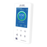
The AFA4000/E monitor can be mounted on either side of the fume cupboard. However, when
deciding on the location for the airflow monitor, sensor and Econ Power Supply Unit (PSU),
consider the cable lengths required:
• The 14-way ribbon cable must be able to connect the Econ Power Supply Unit when it is
fitted to the top of the fume cupboard to the AFA4000/E controller.
Note: Longer ribbon cables are available on request.
• The mains ac power cable from the Econ Power Supply Unit must be able to reach a
suitable power socket.
• The standard 2 metre ‘telephone style’ sensor cable must reach from the back of the
AFA4000/E airflow monitor to the airflow sensor. When possible ensure that the airflow
sensor is mounted on the same side of the fume cupboard as the AFA4000/E.
Note: Longer sensor cables are available on request.
Note: The Econ VAV damper can be mounted in any orientation, but take into consideration
the access required to the damper for future maintenance.