AFA4000/E VAV Airflow Controller / p.49
5.1.1 SM7 airflow sensor installation notes
It is very important to position the SM7 airflow sensor in the correct position to give a long-term
stable reading of the face velocity.
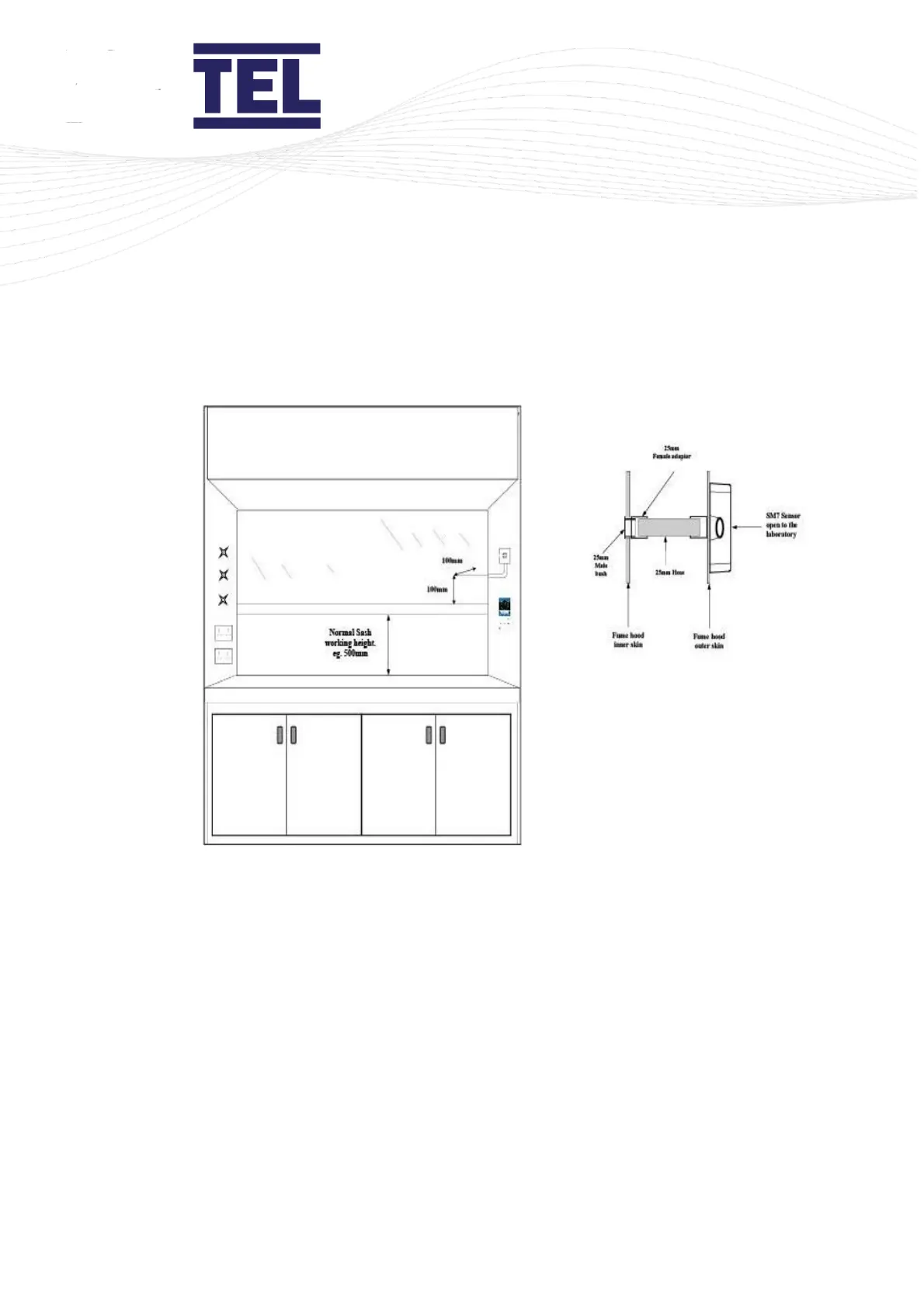
Figure 15: Airflow sensor installation diagram
Please read the notes below and if in doubt contact us for further advice.
1. The SM7 sensor must be positioned where it can sense the room pressure of the laboratory.
The back-connection spigot of the sensor is designed to accept a tube with outside diameter
of 25 mm, which should be connected to the inner chamber of the fume cupboard. This tube
and fittings are known as the ‘vent kit’.
The ideal position for the end of the 25 mm diameter tube, for most fume cupboards, is 100
mm back from the sash glass and 100 mm higher than the normal sash opening height
through the inner side wall.
2. If possible, mount the sensor on the front of the fume cupboard and use a short length of
tube. Tube lengths of more than 1 m or smaller diameter will restrict the airflow through the