AFA4000/E VAV Airflow Controller / p.56
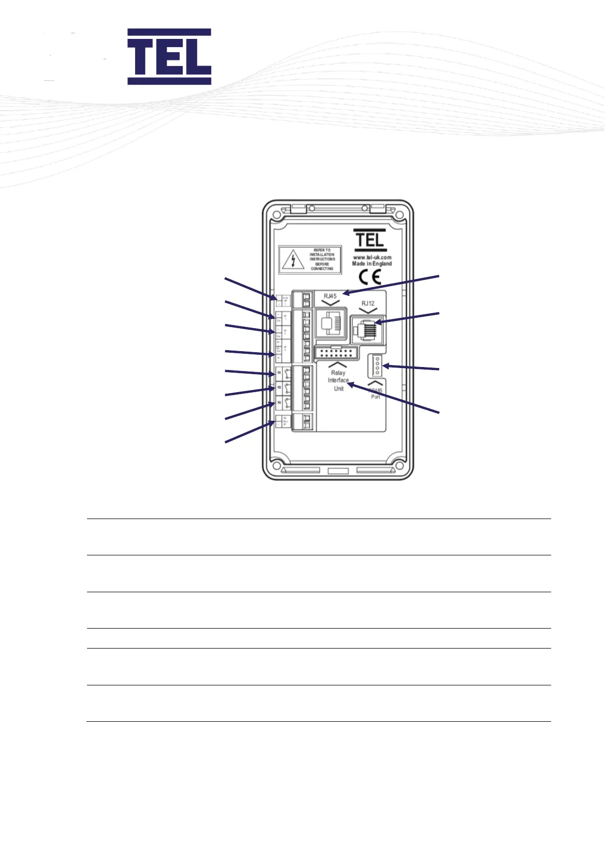
Figure 21: AFA4000/E and AFA4000/E/AS monitor connections
0-10 V Econ Output 1 (used if relay
interface is not fitted)
Relay output 3 (used if relay interface is
not fitted)
Input 1 – digital or analogue
15 Vdc power supply (used if relay
interface is not fitted)
Input 2 – digital or analogue
Auto sash RJ45 connection (only used on
AFA4000/E)
Input 3 – digital or analogue
Airflow sensor RJ12 connection
Relay output 1 (used if relay interface is
not fitted)
14-way ribbon cable connection to relay
interface
Relay output 2 (used if relay interface is
not fitted)
RS485 comms port connection