AFA4000/E VAV Airflow Controller / p.66
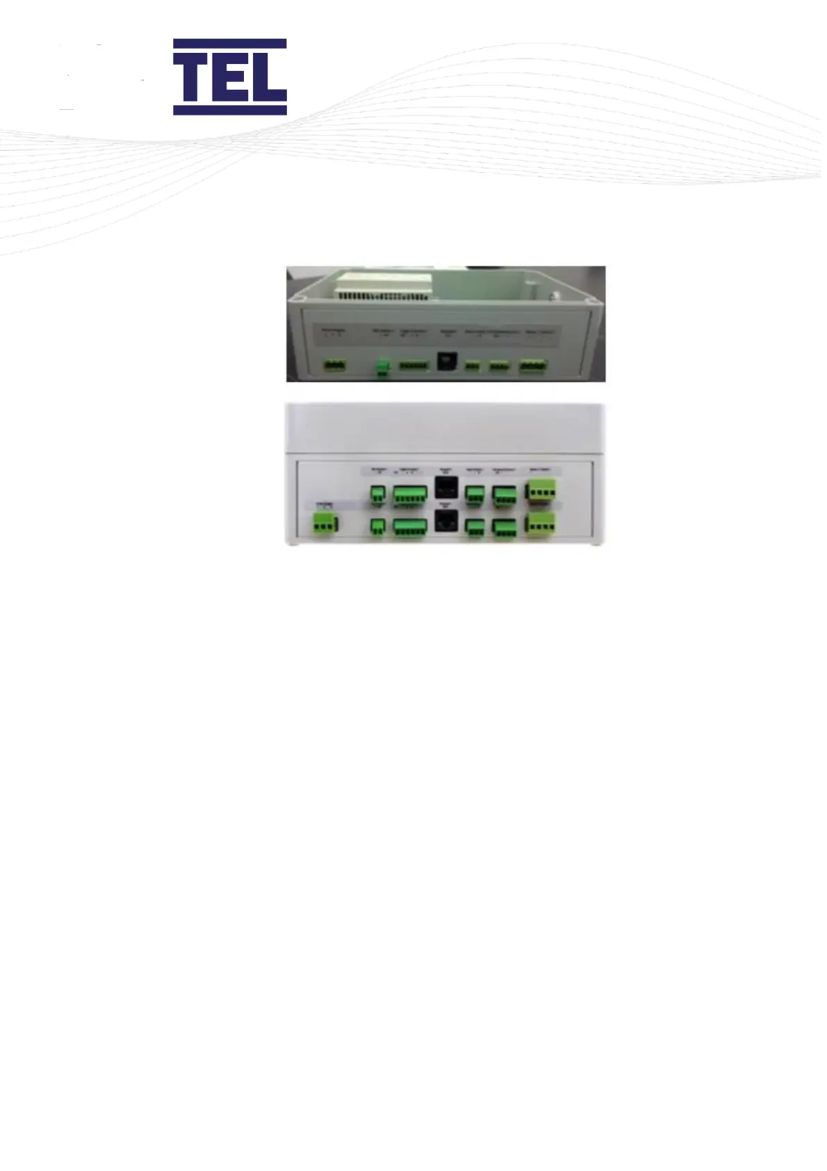
Figure 30: Auto Sash Control Unit Connectors, Single and Dual Fume Hoods
Once the Auto Sash Control Unit has been positioned, mark its position using the fixing holes in
the rear of the housing as a template. Then, attach the Auto Sash Control Unit using screws.
6.1.2 Wiring in the Auto Sash Control Unit
For fume hoods with an inner and outer sidewall, route all cables through the sidewall and into
the service void.
For fume hoods with a single wall, route all cables up the outside of the sidewall, using suitable
trunking or fixing pads and ties.
When wiring in the Auto Sash Control Unit, observe the following:
• Keep cables clear of moving parts.
• Use grommets wherever cables pass through sidewalls to prevent abrasion of the cable
insulation and / or sidewall. Where a cable is supplied with a DIN connector, the grommet
should have a minimum internal diameter of 17mm (0.67").
• Do not overstress cables by bending, for example when passing at 90° through a sidewall.