AFA4000/E VAV Airflow Controller / p.70
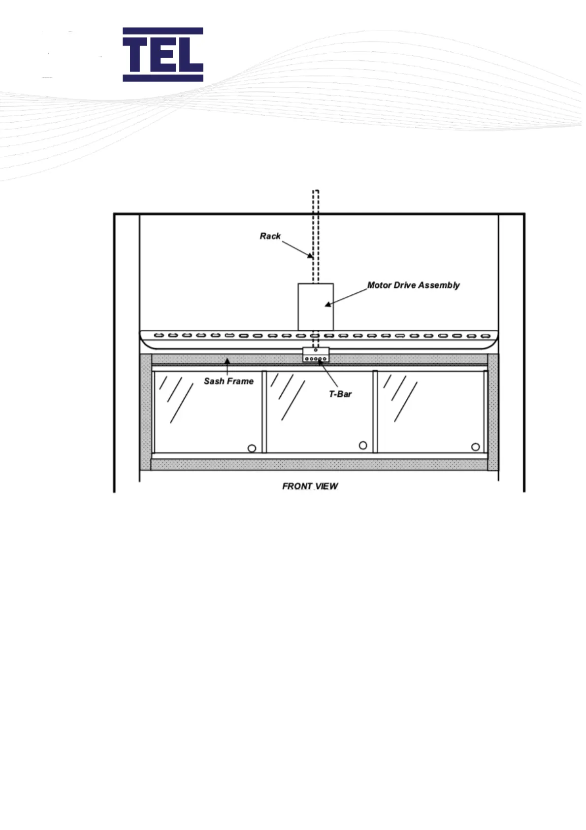
Figure 33: Front view of rack and pinion sash drive
6. When fitting a sash low switch instead of a sash position sensor, the rack will need to be cut
to the correct length to enable the switch to operate.
Close the sash fully and mark the rack just below the position of the proximity low switch at
the top of the motor assembly to ensure that the rack is clear of the switch when the sash is
closed.
7. Connect the Sash Drive to the Auto Sash Control Unit using the cables provided (with red and
black connectors). See the wiring schematic in section 6.9.
Note: It is important to observe the correct polarity when making electrical connections.
8. Connect the clutch assembly to the Auto Sash Control Unit using the cables provided (with
blue and yellow connectors).