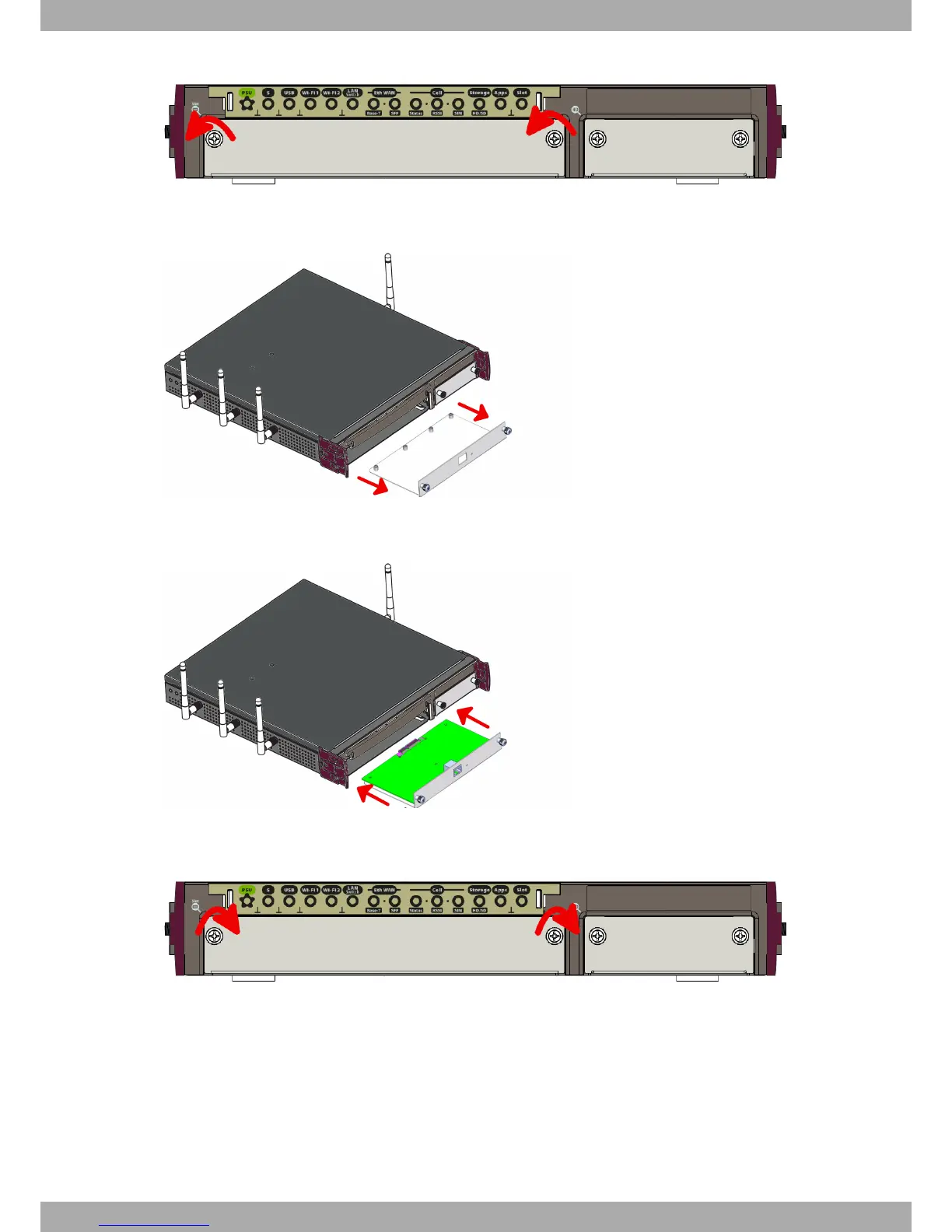
Fig. 7: Unscrewing the front panel screws
(4) Once unscrewed, pull the tray out of the front panel slot.
Fig. 8: Extracting the tray from the front panel
(5) Finally, put the tray that holds the card back into the device.
Fig. 9: Inserting the expansion card
(6) Screw the tray to the device.
Fig. 10: Screw the tray to the front panel
(7) Connect the equipment as indicated in section 3.5.1.1 "Connecting". Connect a terminal to the console and veri-
fy that the expansion card has been detected.
3.3 Installation in a rack
The Teldat iM8 device can be installed in a 19” rack. The necessary strips and screws are not provided by default
and have to be acquired separately.
(1) First, remove the side tabs to free the screws holes:
Teldat S.A.
3 Components and Power Supply
Teldat Router iM8 9