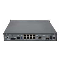
Fig. 17: Removing the screws from rear panel
(4) Once the screws have been removed, slide the flap and lift it to remove it. Place it in a safe location.
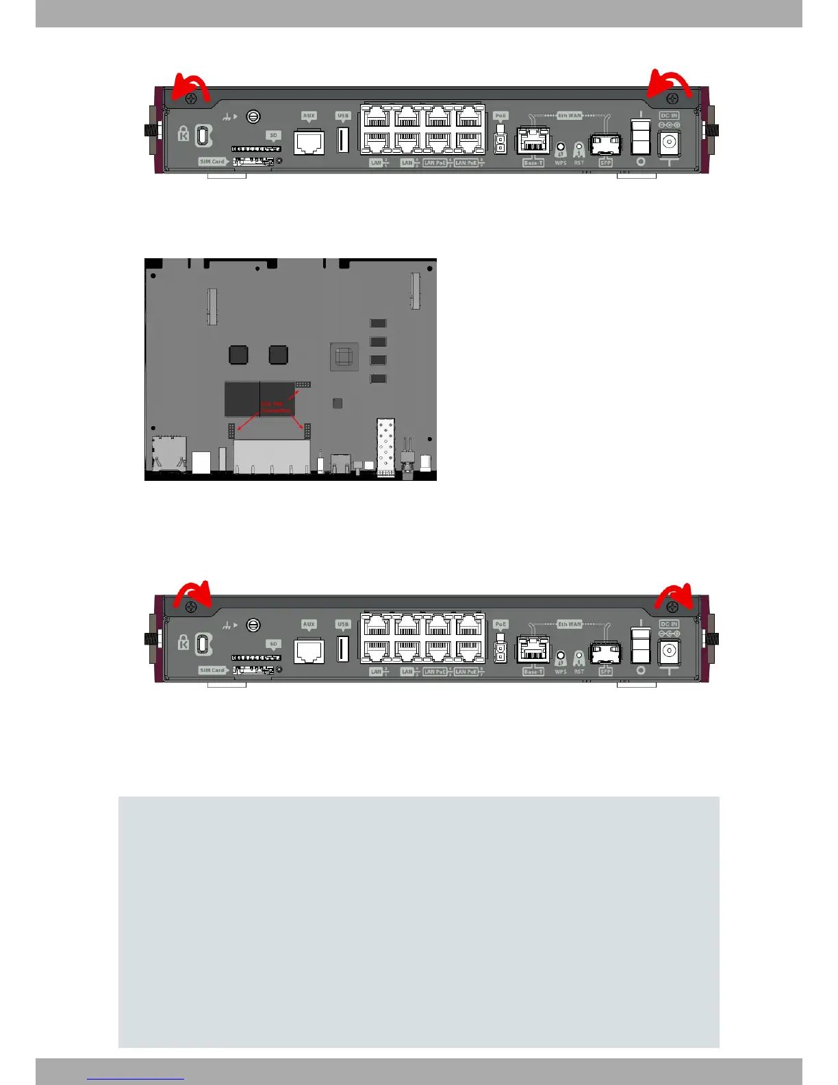
(5) Find the place where the MiniPoE card needs to be located.
Fig. 18: MiniPoE card: Location
(6) Place the MiniPoE card so that it matches the three connectors. This operation must be carried out carefully,
without forcing any piece or part of the device. Check that the card is firmly placed over the connectors.
(7) Put the top panel flap back and screw it into place using the screws.
Fig. 19: Rearranging the top panel’s flap screws
(8) Connect and switch on the device, as described in Connecting on page 13. Should you detect any problems,
switch off the device and make sure that the above steps have been carried out correctly. If the problem per-
sists, please contact your usual supplier.
(9) Connect a terminal to the console and check that the device detects the MiniPoE card.
**************************************************
**************************************************
**************************************************
BIOS CODE DUMP..................
BIOS DATA DUMP....
End of BIOS dump
Boot-stack used: 0x000007D8
Boot-stack free: 0x00001828
!!!!! ******************************* !!!!!
!!!!! ********* DEBUG BIOS ********** !!!!!
!!!!! ******** ONLY FOR R&D ********* !!!!!
!!!!! ******************************* !!!!!
FLASH BIOS CODE VERSION: 01.05 Jan 13 2017 12:28:02 L0
Current date: Feb 23 2011, Wednesday Current time: 10:11:06
3 Components and Power Supply Teldat S.A.
14 Teldat Router iM8