MCC201/MCC201H User manual
System Connections
MCC201 operates as one of two modes; as Encoder or Decoder. MCC201 systems can be connected in
either 1-to-1 fashion where one encoder is connected one decoder or 1-to-many fashion where one encoder
connected to many decoders.
Following chart shows data status of video, audio and serial data on each mode.
System Mode Video Audio Serial Data
Encoder Transmit Transmit/Receive Transmit/Receive
Decoder Receive Transmit/Receive Transmit/Receive
Therefore, the system modes are defined by the video communication and all system modes are capable of
bi-directional transmission of audio or serial data.
Topology
Generally, the encoder and a decoder are connected in 1-to-1 mode. To support specific situation,
1-to-multiple connection is also supported.
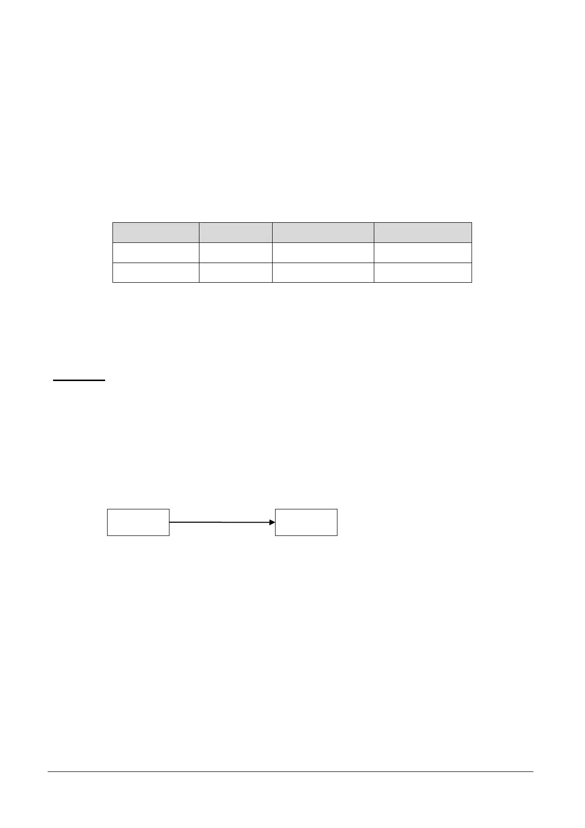
1:1 Connection (Unidirectional Transmission).
The most commonly used configuration is 1 to 1 connection. An encoder is installed at a site where video
images can be transmitted and a decoder is installed at a center location to receive and view the video images
on monitors. Audio and serial data are transferred in either direction.
A decoder and encoder can be connected by setting the encoder’s address at the decoder’s remote IP.
Encoder Decoder
Remote Center