Reproduction forbidden without Telit Communications S.p.A. written authorization - All Rights Reserved page 48 of 93
6.5.2 Transmission line measurements
HP8753E VNA (Full-2-port calibration) has been used in this measurement session. A
calibrated coaxial cable has been soldered at the pad corresponding to RF output; a
SMA connector has been soldered to the board in order to characterize the losses of
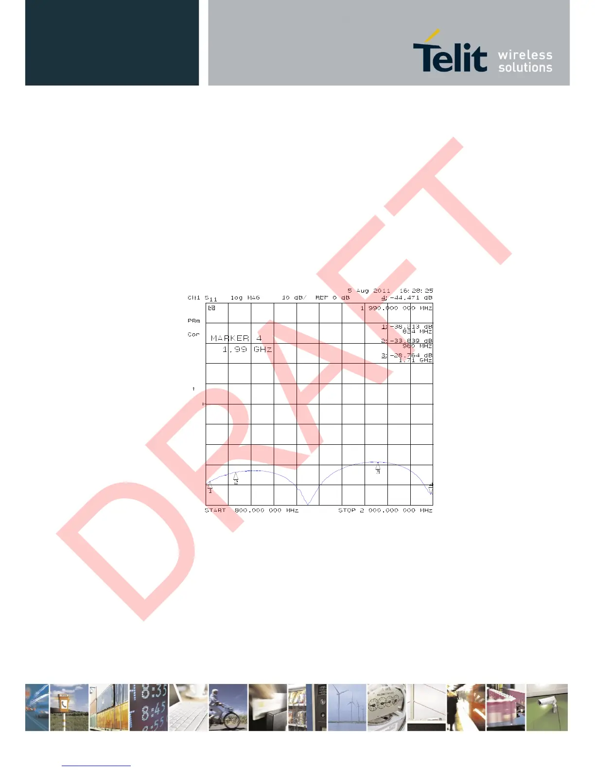
the transmission line including the connector itself. During Return Loss / impedance
measurements, the transmission line has been terminated to 50 Ω load.
Return Loss plot of line under test is shown below: