Reproduction forbidden without Telit Communications S.p.A. written authorization - All Rights Reserved page 58 of 93
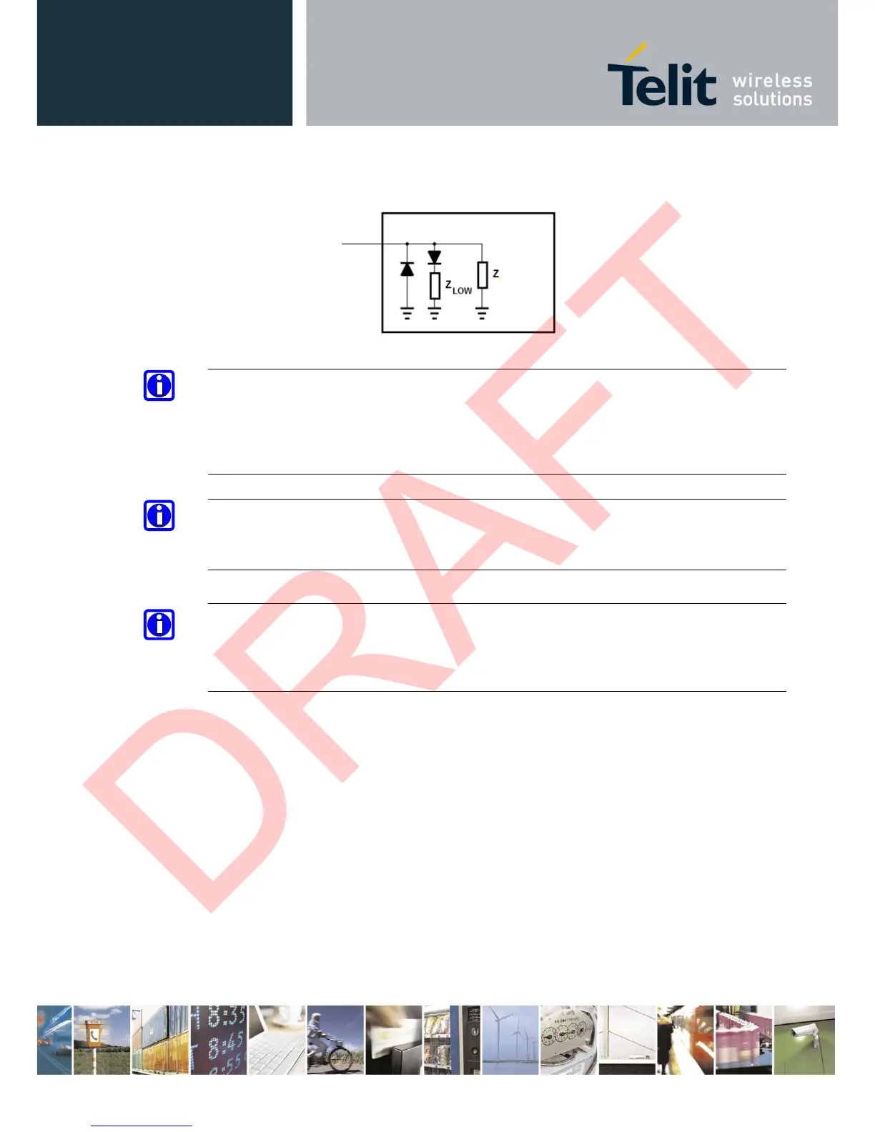
The input line ON_OFF and RESET state can be treated as in picture below
NOTE:
According to V.24, some signal names are referred to the application side, therefore on the
UE910 side these signal are on the opposite direction:
TXD on the application side will be connected to the receive line (here named C103/TXD)
RXD on the application side will be connected to the transmit line (here named C104/RXD)
NOTE:
For a minimum implementation, only the TXD, RXD lines can be connected, the other lines can
be left open provided a software flow control is implemented.
NOTE:
In order to avoid a back powering effect it is recommended to avoid having any HIGH logic
level signal applied to the digital pins of the UE910 when the module is powered off or during
an ON/OFF transition.
 Loading...