TEM A07EXXXX – 1 Unit Transmitters Page 23
8 INSTALLATION
8.1 Unpacking and inspection
Immediately, after the transmitter has been delivered, please carefully check the package to verify possible
damages caused by shipment. Should be found some damages, please immediately contact the T.E.M. dealer.
It is recommended to keep the original package for a future shipment due to, for instance, repairing or setting. A
return with a package which is different from the original one will make the warranty rights lost.
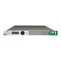
8.2 Installation
The transmitters A07E0XXX are composed of a 19 inches width rack which takes 1 unit in height in a vertical rack
mount.
It is recommended to use 4 fixing plastic washers in order to avoid damages to the front panel varnishing. We
remind to carefully connect the earth both to the transmitter and to the rack mount- never disconnect it without
having switched the supply voltage off by the mains switch.
Design has considered the new rules concerning the electromagnetic compatibility so there aren’t problems to
locate systems CE marked nearby.
8.3 Power supply
AC power supply at 50Hz can be at 230V
AC
single phase.
The switching on control is placed for security reasons on the rear panel with exciter protection fuse, which must
have the value 5A (50-100W Models),8A ( 300-500W Models) and delayed type.
BEFORE SWITCHING THE TRANSMITTER ON, MAKE SURE THAT:
THE AC MAINS POWER SUPPLY IS CORRECT,
THE GROUND CONNECTION IS PRESENTE AND CONNECT
THE RIGHT LOAD OR ANTENNA!
8.4 Ground loops
Sometimes connecting various ground sockets having different potentials may produce some unwanted loops,
which may create hum in the modulation: in this case it is essential to firstly identify the origin of these currents,
which normally spring from the antenna ground, mains supply ground or from the input low frequency signals
ground.