www.temcoline.com
DIGITAL PID CONTROLLER
16
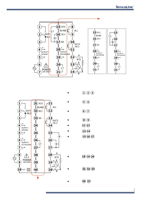
※ Terminal explanation (T59-S10 basis)
Terminal : OUT1 only for output
selection no. 0, 3 (Relay output) mode.
Terminal : OUT1 only for output.
selection no. 1, 2 (SSR, SCR output) mode.
Terminal : RET(Retransmission 4~20mA)
or for power of sensor SPS. (DC 15V)
Terminal : Power supply terminal.
Terminal : Alarm1 output terminal.
Terminal : Alarm2 output terminal.
Terminal : C.T(800:1) input terminals
for Heater break alarm.
Terminal : It is an external input (DI)
terminal. various functions can be set with
external switches according to DIS 1-5 (1: OFF,
2: SV 1-3, 3: run / stop 4: 4: auto / manual
5: alarm reset).
Terminal : The input sensor type is
changed according to the input setting number
with the univeral input terminal.
Terminal : RS-485 communication
terminals completely isolated, Modbus-ASCII,
Modbus-RTU, PC-Link, TL-Link basic.
D.I 1
D.I 2
D.I 1
D.I 2
OPTION
OPTION 1 (T59-C1X)
3) T57 (72x72 mm)
4) T59 (96x96 mm)
T57
T59
OPTION 1
(T57-C1X)
OPTION 2
(T57-C2X)
D.I 1
D.I 2