www.temcoline.com
DIGITAL PID CONTROLLER
19
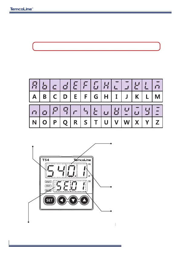
2) 7 Segment display indications
7. Check points before Using
1) Default values at the point of manufacture
The default input and output values of the product at the point of manufacture
are as follows.
Input : K-Type (Code No. 1) Output : SSR (Code No. 1)
※ In the case of the basic model of T54-S00 only, when SSR(1) or SCR(2) is chosen
as the output mode, Alarm 1 output will be in main relay.(Refer to page 8 for
details.)
3) Initial display on power supply (T54 SERIES basis)
Model Name
Firmware version display
Output type indication
Input type indication
0 :
Basic type (No option)
1
:
RET, ALARM1, 2
2 : HBA(CT), ALARM1, 2
3 : DI, ALARM1, 2
4 : RET, RS-485
5 : HBA(CT), RS-485
6 : DI(SV1, 2), RS-485
7 : RS-485, ALARM1, 2
0 : RELAY ON/OFF control
1
:
SSR (
VOLT-PULSE) PID control
2 : SCR (4~20mA) PID control
3 : RELAY PID control
01
: K-Type (-200~1370 ℃)
02 :
K-Type (-199.9~999.9 ℃)
33 :
mV DC (0~100mV)
Option indication