3-21
Controls and Operating
MANUAL AUTO POWER ECONOMY
1
2
3
4
5
D
N
R
1
R
2
7
3
9
1
2
8
5
4
6
1630
VIEW ON FRONT OF
INTERFACE BOX
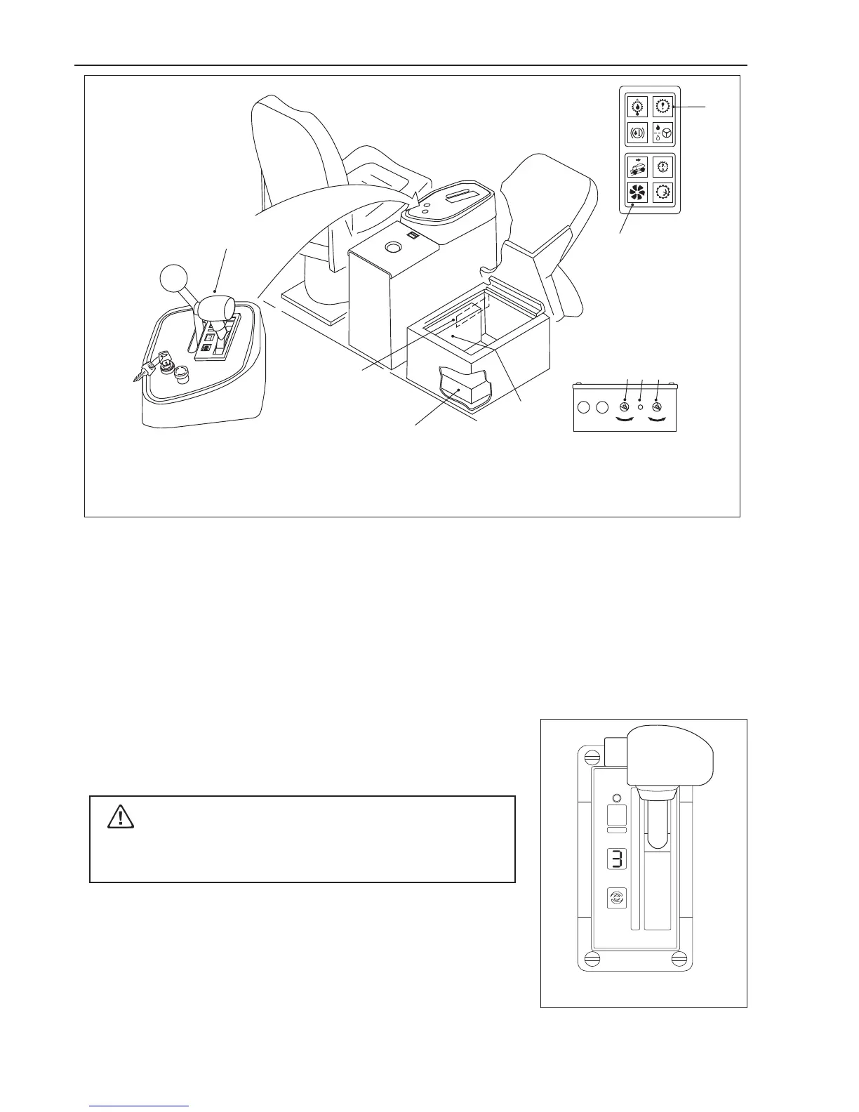
DESCRIPTION AND OPERATION
1. Electronic Control Unit (ECU)
Contains an electronic microcomputer. The ECU receives information in the
form of electronic signals from the switches and sensors, processes the
information, and sends electronic signals to the appropriate solenoids which
control the transmission.
2. Electrical Control Box
Contains fuses and relays.
3. Gear Shift Selector
The shift selector is a remote mounted lever type. The gear shift selector is
connected to the ECU by a wiring harness. The shift lever has 6 forward
ranges and 1 reverse range, as well as a neutral position.
Do not allow the vehicle to coast in Neutral. This practice can
result in severe transmission damage.
The shift selector has a single digit LED display, that during normal
operation will display the gear selected (
Not gear attained
). Diagnostic
information can be displayed on the single digit LED display by pressing the
diagnostic display button. There is a hold override button that must be pressed
when shifting between R, N and D. The hold override button is released
when desired selector position is reached. The selector lever can move
freely between D and the number ranges without pressing the hold override
button.
Gear Shift Selector
1476
1. Electronic Control Unit (ECU)
2. Interface Box
3. Gear Shift Selector
4. Mode Selection Switch
5. Manual Mode Switch
6. Manual Mode Warning Light
7. Check Trans Warning Light
8. In-converter Indicator Light
9. Digital Data Line
1
2
3
4
5
D
N
R
MODE
1
R
2