42 CBLé System Guidebook
About CMD3—Sample and Trigger Setup
(Continued)
Trigger Threshold
This parameter defines the voltage level required from the input signal to
begin triggering. It is also used to set the threshold for counting signal
transitions when measuring period and frequency.
This parameter does not apply when:
¦ Operation 5 (Period) or 6 (Frequency) is not selected in
CMD1
, and
Trigger Type is 0, 1, 6, or 1nnnn.
¦ External Clock is 0.
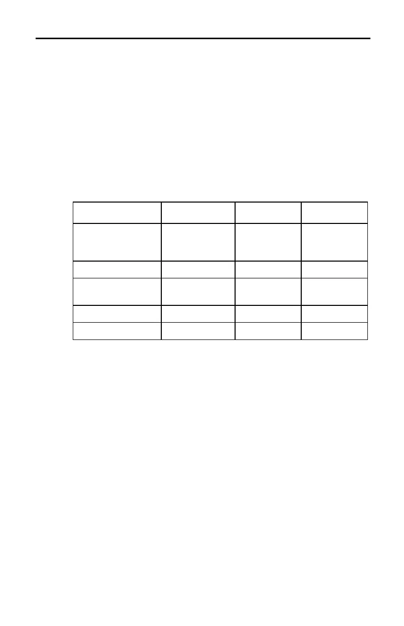
The table below shows valid Trigger Threshold values and other
parameters required to use Trigger Threshold. (Default: see boldface
text below.)
Trigger
Threshold Values
(CMD1)
Operation Trigger Type
Trigger
Channel
1 (Volt)
1 (Amp)
1 (Kohms)
2, 14
2
3
4
2, 3, 4, 5 1, 2, 3, 21
L10 to 10 (Volts)
1
2, 14
2
2, 3, 4, 5 1, 2, 3
L10 to 10 (Volts)
1
5, 6 0, 1, 2, 3, 4, 5,
1nnnn
n/a
L10 to 10 (Amps)
1
3 2, 3, 4, 5 1, 2, 3
1 to 100 (Kohms) 4 2, 3, 4, 5 1, 2, 3
1
Applies to CH1 and CH2 only.
2
Operation 14 (0–5 Volts) applies only to software triggering.
Note: If there is a conflict between the value entered in Trigger
Threshold and the operation selected in
CMD1
, you will get an E.36 error
message (page 57).
There are two types of thresholds that can be set—hardware triggering
and software triggering. (Refer to page 71 for additional information.)