CBLé System Guidebook 69
Digital Output Buffer
The Digital Output Buffer (
DOB
) is a circular buffer that contains up to
22 data elements. The output from the
DOB
is a 4-bit (TTL 0–5 Volts)
digital nibble (refer to “Digitial Nibble” in the Glossary, if necessary) for
each data element. For example, 0 = 0000, 1=0001, 2=0010, 10=1010,
15=1111. One digital nibble appears at
DIG OUT
on the D0–D3 lines at
each sample time. (Refer to the diagram below.)
The drive (output current) capability for nibble data and the clock is
shown by the following:
¦ V
output-high
> 3.98 Volts @ I
output-high
> L6ma (negative current flow
out of the CBL)
¦ V
output-low
< 0.26 Volts @ I
output-low
< 6ma (positive current flow
into the CBL port)
The number of times that the DOB outputs the contents of the buffer
depends on the number of data elements defined in
CMD1
and the
number of samples defined in
CMD3
.
Digital Output Buffer Example
CMD1
list is {1,31,5,1,2,3,4,5},
where:
CMD3
list is {3,1,100}, where:
1=Channel Setup.
31=
DIG OUT
.
5=Five data elements.
1=0001 (digital nibble).
2=0010 (digital nibble).
3=0011 (digital nibble).
4=0100 (digital nibble).
5=0101 (digital nibble).
3=Sample and Trigger Setup.
1=One second sample time.
100=One hundred samples.
(Trigger Type defaults to manual
triggering.)
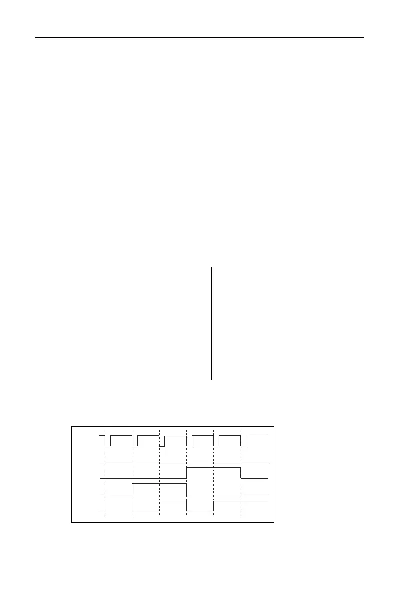
The DOB outputs pulses that correspond to the five digital nibbles
(1234512345...12345 etc.). This sequence is repeated 20 times (100
samples/5 data elements) to the
DIG OUT
channel. The diagram below
shows a portion of this output for the first five data elements.
Sample
Clock
1234
5
1
D3
D2
D1
D0
Sample
Clock
 Loading...