80 CBLé System Guidebook
CMD3—Sample and Trigger Setup
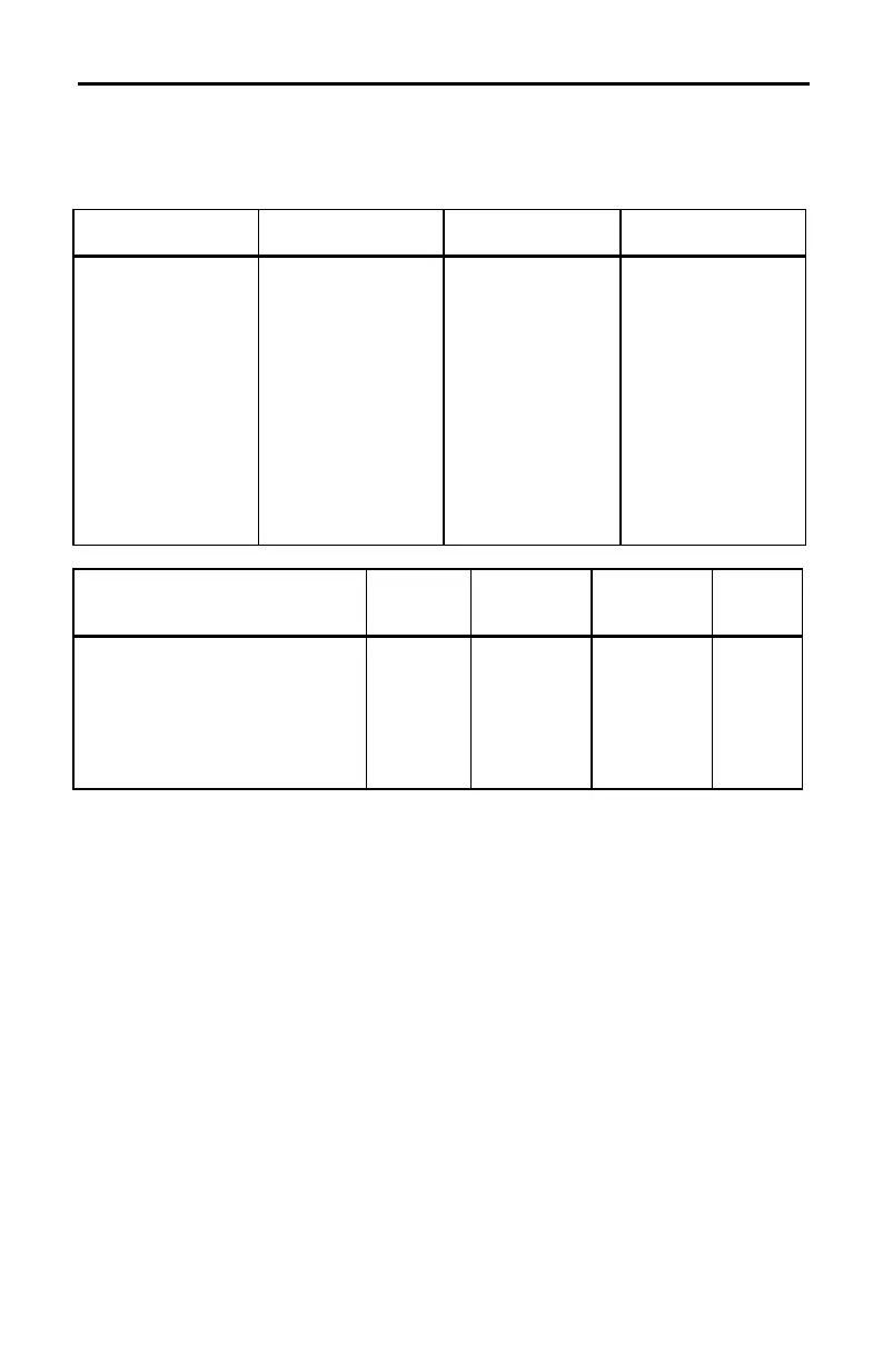
CMD3 Syntax and Parameters
{3,sample_time,number_samples,trigger_type,trigger_channel,
trigger_threshold,prestore, external_clock,record_time,filter}
Sample Time (sec)
Number of
Samples
2
Trigger Type
3
Trigger Channel
0.5
0 = External clock
1
–
.25–16000
1–512
L
data collection following
"CBLGET" instruction.
0= None
1= Manual
NN
N
5= N +
sample
n= 2–9 is don’t care.
0= n/a
1–3, 21
1–3= Analog Input
21= External Clock
3
Trigger Threshold
4
Prestore
Data %
External
Clock
Source
Record
Time Filter
5
0 = N/A
if trigger = 0, 1, 6, or digital
J
if Trig. Type = 2, 3, 4, 5,
and Trig. Channel = 1, 2, 3, 21.
L
10 to 10 Volts if volts selected.
L
10 to 10 Amps if current selected.
1 to 100 Kohms if resistance sel.
0–100%
clock
input, CH1
0= None
1= Absolute
2= Relative
0–6
1
Range restrictions apply. (See “Sample Time” on page 51, and Appendix A,
“Determining the Minimum Sample Time.”)
2
Limit is 256 if Stats is selected in
CMD1
.
3
If the trigger type is a digital nibble,
CH21
is automatically selected as the trigger
channel regardless of value enter for Trigger Channel.
4
The trigger threshold for period and frequency is limited to 7 levels (5.0, 1.0, 0.2, 0,
L0.2, L1.0, L5.0 for voltage and corresponding values for current and resistance). The
trigger threshold in the setup string is rounded to the nearest value.
5
If
CH31
or Stats is requested, or number of samples is L1, the default (no filtering) is
used.