March 2009 SNAU028A 23
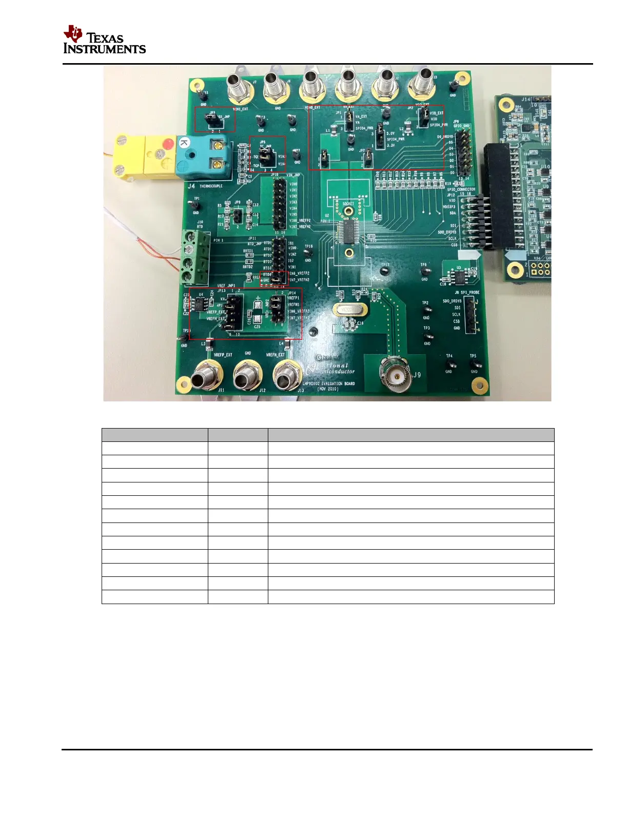
Figure 21 – Jumper Settings for the Thermocouple and LM94022 Example
Source VA with the 5.0V from the SPIO-4 board.
Source VIO with the 5.0V from the SPIO-4 board.
Get 5.0V from the SPIO-4 board
Connect VA supply to the LMP90100
Connect VIO supply to the LMP90100
Connect the output of LM94022 to VIN5
VREFP1 = 4.1V from U4 (LM4140)
Connect VREFP1 source to the LMP90100
Connect VREFN1 source to the LMP90100
Table 4 – LMP90100EB Jumpers for the RTD Application
D. Installing/Opening the Software – skip this step if it’s already done. If not, follow section 9.0
to install and open the LMP90100 Sensor AFE software.
E. Connecting and Powering the Boards
1. Connect the LMP90100EB to the SPIO-4 board as seen in Figure 4.