www.ti.com
Setup
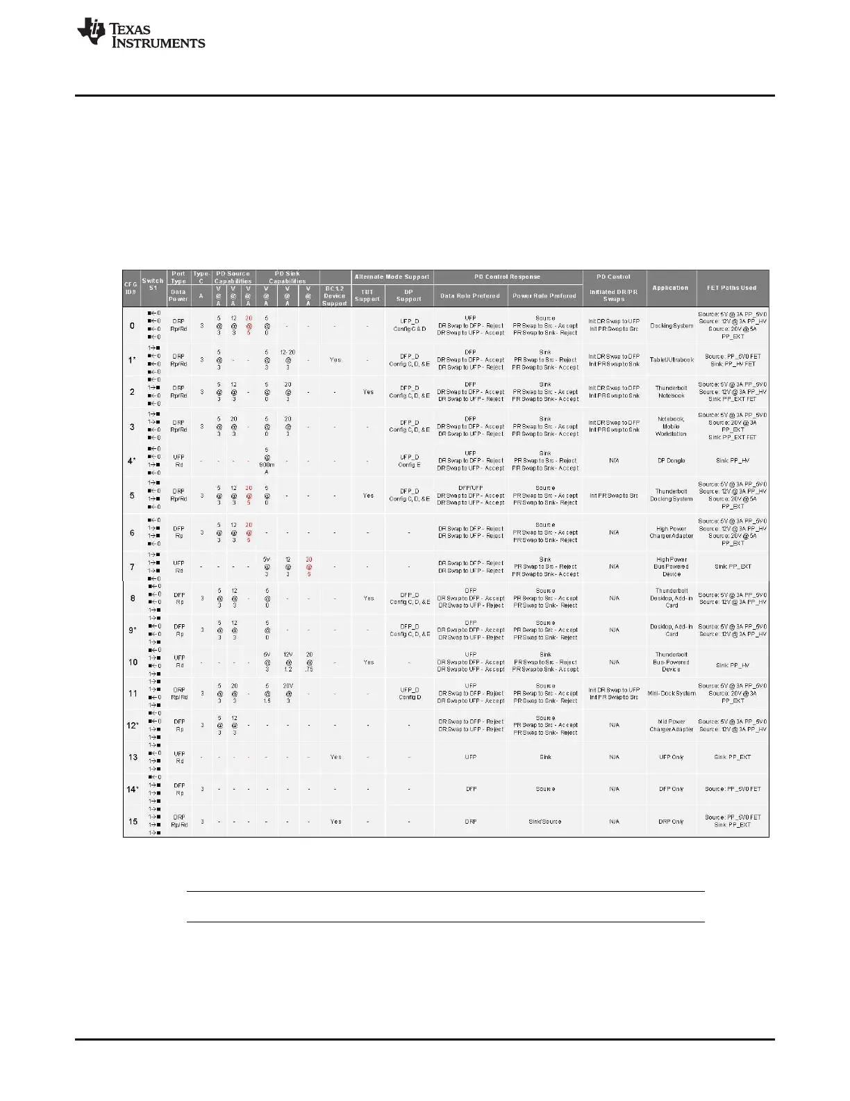
5.3.3 TPS65982-EVM Configuration Table Overview
Configuring the TPS65982-EVM to power-on, initialize, and emulate application types is outlined in
Table 2, and is as simple as changing the position of the top 3 DIP switches on switch bank S1. Resetting
the TPS65982 IC (U2), reloading the FW in the Flash IC (U1), and re-initializing by reading the S1 DIP
switch positions can be accomplished by pressing and releasing push-button S3. A detailed description of
each of the TPS65982-EVM configurations settings controlled by S1 can be found in Section 5.3.3.1
through Section 5.3.3.16.
Table 2. TPS65982-EVM Configuration Table
* Configuration compatible with the TPS65986
NOTE: To achieve 5 A, an active or electronically marked cable is needed.
13
SLVUAF8C–June 2015–Revised November 2015 TPS65982 Evaluation Module
Submit Documentation Feedback
Copyright © 2015, Texas Instruments Incorporated

 Loading...


