Firmware Loaded
Wait for Plug
Plug
Detected?
no
Detect Type and
Orientation
yes
C_CC1 =
Data line?
no
Connect
C_CC2 to
USB-PD Phy
C_CC1 Open
yes
Connect
C_CC1 to
USB-PD Phy
C_CC2 Open
C_CC2
Powered?
C_CC1
Powered?
no no
Connect C_CC2
to PP_CABLE
Connect C_CC1
to PP_CABLE
yes yes
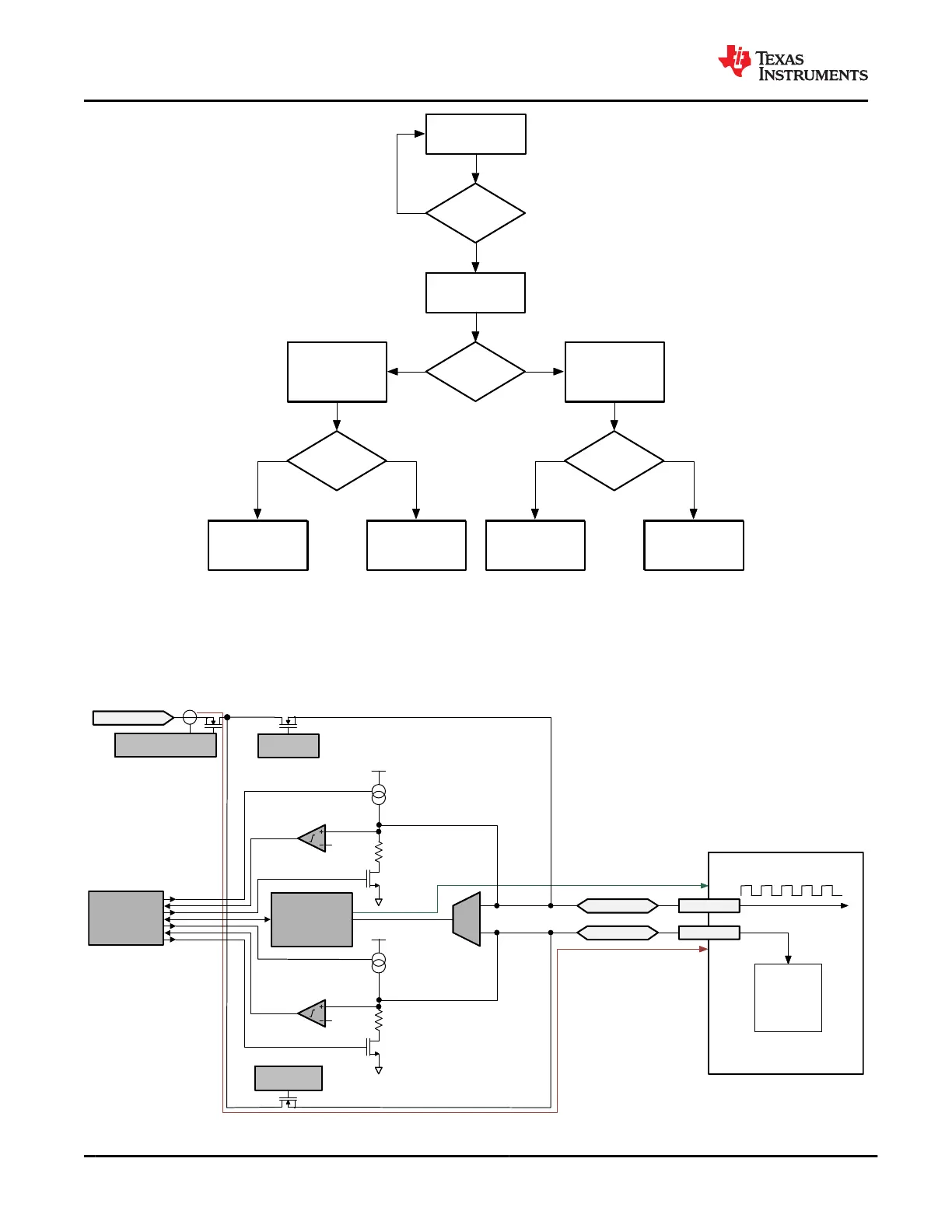
Figure 9-28. Port C_CC and VCONN Connection Flow
Figure 9-29 and Figure 9-30 show the two paths from PP_CABLE to the C_CCn pins. When one C_CCn pin is
powered from PP_CABLE, the other is connected to the USB-PD BMC modem. The red line shows the power
path and the green line shows the data path.
Cable Plug
Active
Cable
Circuitry
USB-PD Data
Power
CC
VCONN
USB-PD
Digital Core
Phy
LDO_3V3
LDO_3V3
C_CC2
C_CC1
PP_CABLE
C_CC1 Gate
Control
Fast
current
limit
C_CC2 Gate
Control
C_CC1/2 Gate Control
and Current Limit
Figure 9-29. Port C_CC1 and C_CC2 Normal Orientation Power from PP_CABLE
TPS65982
SLVSD02E – MARCH 2015 – REVISED AUGUST 2021
www.ti.com
50 Submit Document Feedback
Copyright © 2021 Texas Instruments Incorporated
Product Folder Links: TPS65982