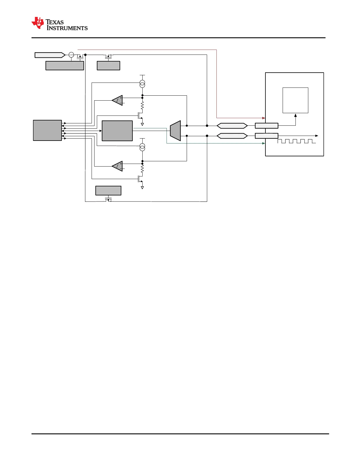
Cable Plug
Active
Cable
Circuitry
USB-PD Data
Power
CC
VCONN
USB-PD
Digital Core
Phy
LDO_3V3
LDO_3V3
C_CC2
C_CC1
PP_CABLE
C_CC1/2 Gate Control
and Current Limit
C_CC1 Gate
Control
Fast
current
limit
C_CC2 Gate
Control
Figure 9-30. Port C_CC1 and C_CC2 Reverse Orientation Power from PP_CABLE
9.3.3.22 PP_CABLE to C_CC1 and C_CC2 Switch Architecture
Figure 9-11 shows the switch architecture for the PP_CABLE switch path to the C_CCc pins. Each path provides
a unidirectional current from PP_CABLE to C_CC1 and C_CC2. The switch structure blocks reverse current
from C_CC1 or C_CC2 to PP_CABLE.
9.3.3.23 PP_CABLE to C_CC1 and C_CC2 Current Limit
The PP_CABLE to C_CC1 and C_CC2 share current limiting through a single FET on the PP_CABLE side of
the switch. The current limit ILIMPPCC is adjustable between two levels. When the current exceeds ILIMPPCC,
the current-limit circuit activates. Depending on the severity of the over-current condition, the transient response
will react in one of two ways: Figure 9-31 and Figure 9-32 show the approximate response time and clamping
characteristics of the circuit for a hard short while Figure 9-33 shows the approximate response time and
clamping characteristics for a soft short. The switch does not have reverse current blocking when the switch is
enabled and current is flowing to either C_CC1 or C_CC2.
www.ti.com
TPS65982
SLVSD02E – MARCH 2015 – REVISED AUGUST 2021
Copyright © 2021 Texas Instruments Incorporated
Submit Document Feedback
51
Product Folder Links: TPS65982