©Copyright Task Force Tips LLC 2004-2018 LIY-200 October 11, 2018 Rev18
17
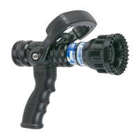
4.3 NOZZLE INSTALLATION
The nozzle is simply screwed onto the monitor’s exit threads. If the nozzle is installed on a Monsoon RC (with electric motors) assure
that the nozzle’s coupling does not make contact with the horizontal drive motor housing when the monitor is in it’s lowest elevation
position.
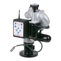
For nozzles with electric pattern control, a cable with a female, waterproof connector is provided at the outlet of the Monsoon RC
which attaches directly to TFT’s electric Masterstream 1250, 1500 or 2000 nozzle. The cable used is a dual-key, micro type plug
assembly. Any other nozzle should have the corresponding male electrical connector installed. Do not cut off the female connector
on the monitor. This connector is molded onto the cable and must remain in place to maintain the water tightness of the electrical
system.
CAUTION
The nozzle threads must match the threads of the Monsoon monitor in both size and type.
Mismatched or damaged threads may cause the nozzle to leak or uncouple under pressure and
could cause injury.
CAUTION
Do not connect aluminum to brass or brass to aluminum. Dissimilar metals coupled together
can cause galvanic corrosion that will freeze the threaded joint or cause complete loss of thread
engagement. If dissimilar metals must be coupled together, the eff ects of corrosion can be greatly
delayed by various coatings on the metal such as powder paint, hard anodizing, or silicone grease.
4.4 PRESSURE GAGE PORT
There is a ¼” NPT female threaded hole on the back of the monitor. The hole is plugged from the factory. If a pressure gage is desired,
unscrew the plug and install the gage using pipe sealant. Make sure the gage does not interfere with the elevation handwheel.
4.5 HANDLE INSTALLATION INSTRUCTIONS
The tiller handle is shipped loose from the monitor and must be installed to complete the installation process. When installing the tiller
handle, be sure to coat the threads of the mounting screw with the Loctite supplied in the hardware packet.
4.6 DRAIN
There is no drain on the Monsoon Monitor itself. A drain valve should be installed on the monitor’s inlet piping.
4.7 LADDER MONITOR INSTALLATION
Due to the unique mounting orientations found on ladder trucks, an anti-back-drive mechanism gearbox is included on ladder models
to prevent unintended monitor/nozzle movement due to vibration. The gearbox allows the motor and manual override wheel to turn
the monitor in both directions, while preventing the monitor from back-driving the motor and manual override wheel. The anti-back-
drive gearbox adds to the size of the monitor (see Figure 3.2E), so additional clearance may be needed to prevent interference with
the cab in some installations. The anti-back-drive gearbox is removable. Contact factory for instructions.
There is also an electronic method to help prevent unintended monitor/nozzle movement due to vibration. This method is provided
for installations where adequate clearance for the anti-back-drive gearbox is not available. The electronic method can only be used
if the monitor is always powered while the truck is in operation. See LIY-500 Section 4.13.3 for wiring and programming information.
5.0 OPERATION
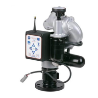
5.1 HORIZONTAL ROTATION CONTROL
A handwheel controls the monitor’s horizontal rotation direction. Clockwise rotation of the handwheel moves the nozzle to the left and
counter-clockwise rotation to the right. Approximately 14 turns of the handwheel will give a 90 degree change in horizontal rotation
direction.
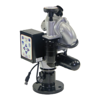
5.2 ELEVATION CONTROL
ELEVATION
HANDWHEEL
ROTATION
LOCK
APPLY FORCE
HERE TO CHANGE
HORIZONTAL ROTATION
A handwheel controls the monitor’s elevation direction.
Clockwise rotation of the handwheel raises the elevation
and counter-clockwise lowers it. About 50 turns of the
handwheel will give the complete 135 degree elevation
travel range of the monitor.
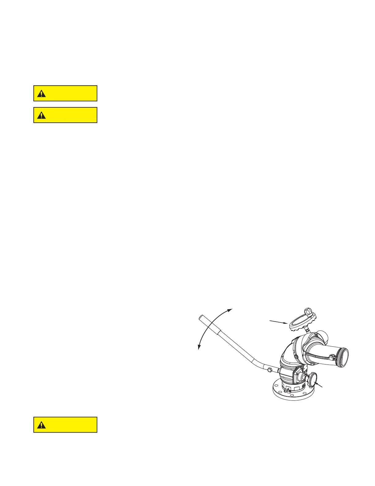
5.3 TILLER BAR MODEL
On the Tiller Bar model the horizontal rotation is changed
by pushing or pulling horizontally on the Tiller Handle.
Twisting the Rotation Locking Knob clockwise will increase
the drag on the lower swivel joint to “lock” the monitor in a
particular direction. See fi gure 5.3 for the Tiller Bar model
controls.
Figure 5.3
Tiller Bar Model Controls
CAUTION
Injury can result from the monitor changing direction due to an off center nozzle reaction. An off
center nozzle reaction may be caused by debris in the nozzle causing an asymmetrical stream.
Always keep the rotation lock tight when not rotating the monitor. Always keep one hand on
the tiller handle when loosening the locking knob. Where continuous 360 degree rotation of the
monitor is not needed it is recommended that the Horizontal Rotation Stop Bolts (see section
4.2.2 for Stop Bolt locations) be installed to reduce any chance of the monitor spinning due to an
off center nozzle reaction caused by debris trapped in the nozzle.
 Loading...