CutMaster a120
OPERATION 4T-34 Manual 0-4989
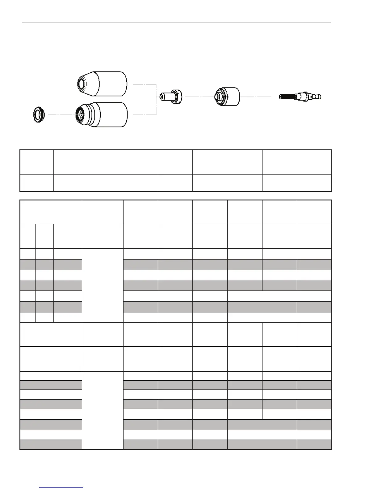
Stainless Steel
120A
Air Plasma / Air Shield
Deector
Standard Shield Cup
Maximum Life Shield Cup
Tip
Starter Cartridge
Heavy Duty Starter
Cartridge
Electrode
9-8243
9-8218
9-8237
9-8233
9-8213
9-8277
9-8232
Material
Thickness
Gas Pressure
(Air)
Arc Voltage
Torch
Working
Height
Travel Speed
Initial
Piercing
Height
Pierce Delay
Kerf Width
@ Rec.
Speed
(GA)
(in) inch
PSI
(torch lead
length)
Volts
(in)
(ipm) (in) (sec) (in)
1/4 0.250
80 (25')
80 (50')
133 0.19 180 0.25
0.20
0.10
3/8 0.375
136 0.19 100 0.25
0.40
0.11
1/2 0.500
140 0.19 60 0.25
0.80
0.11
5/8 0.625
152 0.25 40 0.30
1.20
0.13
3/4 0.750
154 0.25 26 Edge Start 0.14
1 1.000
159 0.25 16 Edge Start 0.14
1-1/4 1.250
167 0.25 8 Edge Start
0.14
Material
Thickness
Gas Pressure
(Air)
Arc Voltage
Torch
Working
Height
Travel Speed
Initial
Piercing
Height
Pierce Delay
Kerf Width
@ Rec.
Speed
(mm)
Bar
(torch lead
length)
Volts (mm) (mm/min) (mm) (sec) (mm)
6
5.5 (7.6m)
5.5 (15.2m)
133
4.8
4800 6.4 0.2 2.6
8 135 4.8 3520 6.4 0.2 2.7
10 137
4.8
2390
6.4
0.5 2.8
12 139 4.8 1750 6.4 0.8 2.9
15 149
6.4
1160
7.6 1.2
3.4
20 155
6.4
625
Edge Start
3.6
25 159
6.4
425
Edge Start
3.6
30 165
6.4
260
Edge Start
3.6
BOLD TYPE indicates maximum piercing parameters. BOLD ITALIC indicates edge starts only.