DRAG-GUN Plasma Cutter 10 Operating Manual 0-2682
F. InterlocksF. Interlocks
F. InterlocksF. Interlocks
F. Interlocks
If supply pressure falls below minimum requirements,
the lockout circuit will open, shutting off the DC Cir-
cuit. Similarly, the overtemp switch will open if the
unit becomes overheated, and will close again when
the unit cools to an acceptable temperature.
G. Parts-in-Place (PIP)G. Parts-in-Place (PIP)
G. Parts-in-Place (PIP)G. Parts-in-Place (PIP)
G. Parts-in-Place (PIP)
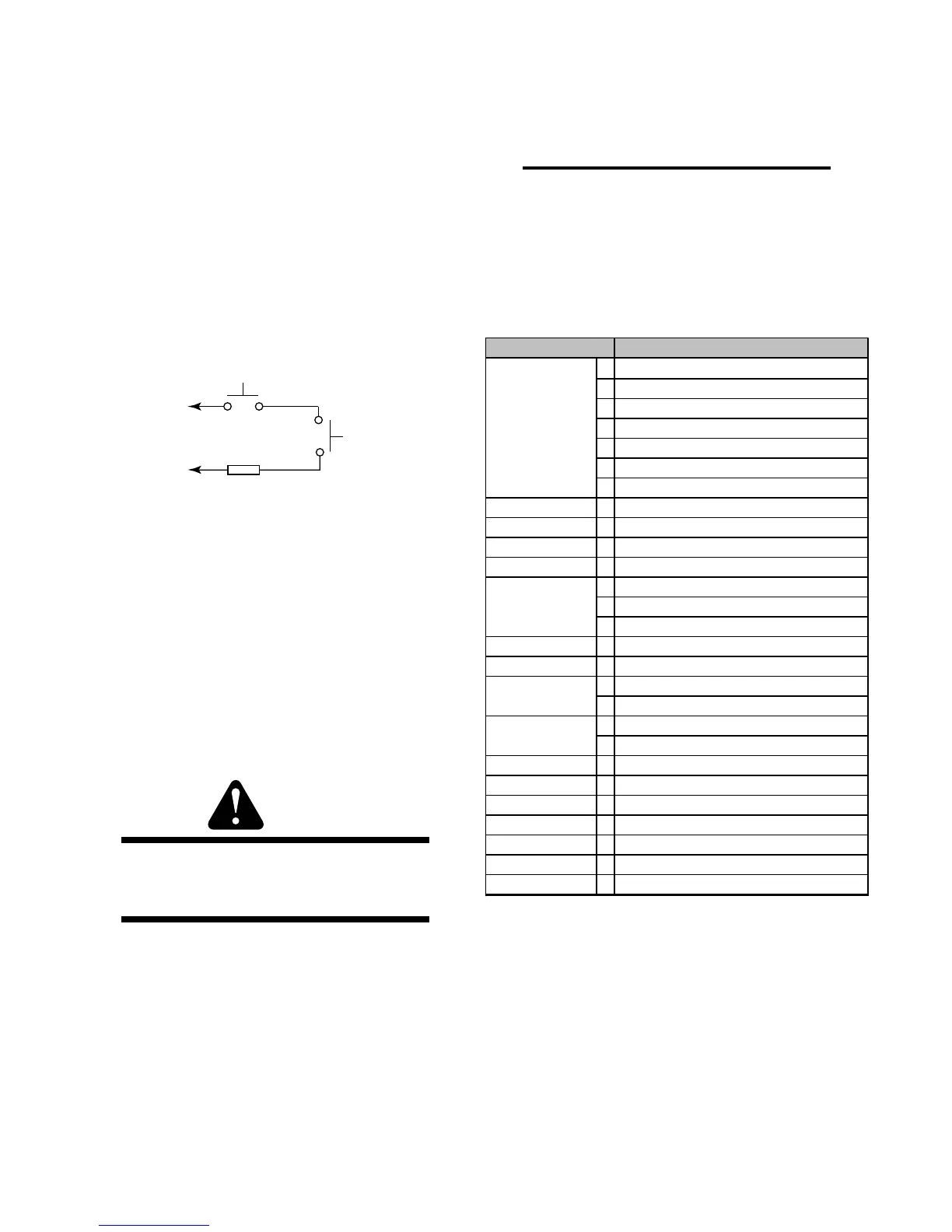
The torch head has replaceable contacts called Parts-
In-Place (PIP). These two contacts are made through
the brass washer inside the shield cup when it is in-
stalled. The torch will fail to operate if these contacts
are not made.
Torch Switch
PIP Pin
PIP Pin
Shield Cup
To Control
Cable Wiring
Butt Splice
A-00784
Figure 2-2 Parts-In-Place (PIP) Diagram
H. Duty CycleH. Duty Cycle
H. Duty CycleH. Duty Cycle
H. Duty Cycle
Duty cycle is the percentage of on-time (measured in
minutes) in a 10 minute period in which a system can
be operated, in an environment of a specified tem-
perature.
Exceeding duty cycle ratings will cause the thermal
overload protection circuit to become energized and
shut down output until the unit cools to normal oper-
ating temperature. Continual exceeding of duty cycle
ratings can cause damage to the cutting power source.
WARNING
When unit shuts down due to thermal overload,
power is still present throughout the entire sys-
tem.
2.2 General Product Description2.2 General Product Description
2.2 General Product Description2.2 General Product Description
2.2 General Product Description
The DRAG-GUN Plasma Cutter is a small, easy-to-use
plasma cutting system which provides 12 amp maximum
output and a cut capacity of up to 1/8" (3.2 mm) of most
metals.
Everything you need to start cutting right away is in-
cluded with the DRAG-GUN - power supply with built-
in air compressor, pilot circuitry, all control circuitry, torch
and work lead (with torch consumable parts installed),
work cable and clamp, primary input cable, extra con-
sumable torch parts, and this instruction manual.
NOTE
The DRAG-GUN Cutter requires no assembly.
2.3 Technical Specifications2.3 Technical Specifications
2.3 Technical Specifications2.3 Technical Specifications
2.3 Technical Specifications
A. System SpecificationsA. System Specifications
A. System SpecificationsA. System Specifications
A. System Specifications
System Specifications
Input Power
100 VAC 50Hz, 110 VAC 60Hz, Single Phase
100/110 VAC, 50/60Hz, Single Phase
120VAC ±10%, 50Hz, Single Phase
120VAC ±10%, 60Hz, Single Phase
220VAC ±10%,50Hz, Single Phase
208/230VAC ±10%, 60Hz, Single Phase
Output Power See subsection 2.3B
Duty Cycle See subsection 2.3B
Maximum OCV 280 VDC
Pilot Circuitry Capacitive Discharge (CD), Constant DC
Weight with Leads 55 lbs (24.9 kg)
Power Supply L 16 in. (406 mm)
Dimensions W 9 in. (229 mm)
H 10 in. (254 mm)
Work Cable 15 ft. (4.6 m)
Input Power Cable 6.6 ft. (2 m) minimum
PCH-10 70°
PCH-10 180°
L See subsection 2.4
W See subsection 2.4
Cutting Rating 12 Amps Max. Straight Polarity
Cut Capacity Most metals up to 1/8 in. (3.2 mm) max.
Severance Most metals up to 3/16 in. (4.8 mm)
Pierce Rating 1/16 in. (1.6 mm)
Transfer Distance Approx. 1/8 in. (3.2 mm)
Gas Requirements Compressed Air (Built-in)
Leads Length 20 ft. (6.1 m)
Torch Style
Torch Dimensions

 Loading...