Page 18 of 29 Revision 3.3 Feb 2021
ProReact EN Analogue Installation Manual
Document Ref. PACC-MAN
Typical System Wiring
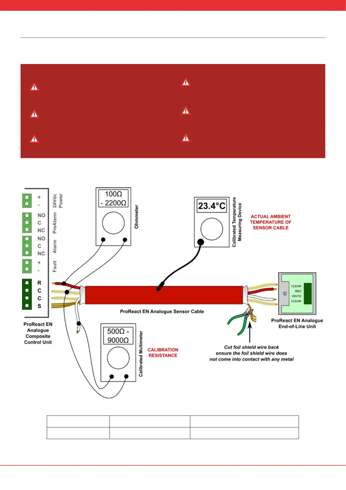
The components of the ProReact EN Analogue LHD system should be connected in the manner shown in Figure 10.
Connect the sensor cable to the end-of-line unit rst then
measure the connections using a calibrated multimeter at
the other end without the cable plugged into the control
unit. The values should match those shown in Table 6.
The connection of the clear cores in the sensor cable into
the ProReact EN Analogue Composite Control Unit are
polarity sensitive. They must go in the correct order (as
shown below).
Make a note of the cable three letter code. Do not mix and
match sensor cables with dierent three letter codes on
the same control unit.
Take care to cut the shield wire back at the end-of-line unit.
Do not mount the end-of-line unit on a metal surface.
The calibration resistance is the value between the white core
and the clear core which is adjacent to the red core in the
sensor cable (as shown in Figure 10).
Record all the sensor cable serial numbers, the sensor cable
three letter reel code and the measured calibration resistance
on the label in the control unit (shown in Figure 10).
Figure 10: Typical System Wiring Diagram for the ProReact EN Analogue LHD System
Table 6. Expected resistance values during commissioning
Red Wire Resistance Red core to adjacent clear core Between 100Ω (0.10kΩ) to 2200Ω (2.20kΩ)
Calibration Resistance Clear core to white core Between 500Ω (0.50kΩ) to 9000Ω (9.00kΩ)