Page 24 of 29 Revision 3.3 Feb 2021
ProReact EN Analogue Installation Manual
Document Ref. PACC-MAN
Testing and Verication
Routine maintenance and checking should be carried out to ensure the
ProReact EN Analogue System is functioning as expected and has not
been damaged.
A visual inspection should be performed to ensure all support brackets
and other aspects of the physical installation are suitable. The cable
should also be visually checked for damage. Check to make sure the
silicone sleeves are correctly installed around the cable in the clips.
Any joints or connections that have been made should be checked to
make sure they are secure and any junction boxes should be checked to
ensure they are correctly installed.
ProReact EN Analogue Composite Control Unit Testing
An analogue test board is included with each ProReact EN Analogue
Composite Control Unit. It is a small PCB that can be plugged into the
sensor cable terminals on the control unit and simulates a 50m length
of sensor cable. It is useful for carrying out regular maintenance on the
control unit, without any sensor cable attached.
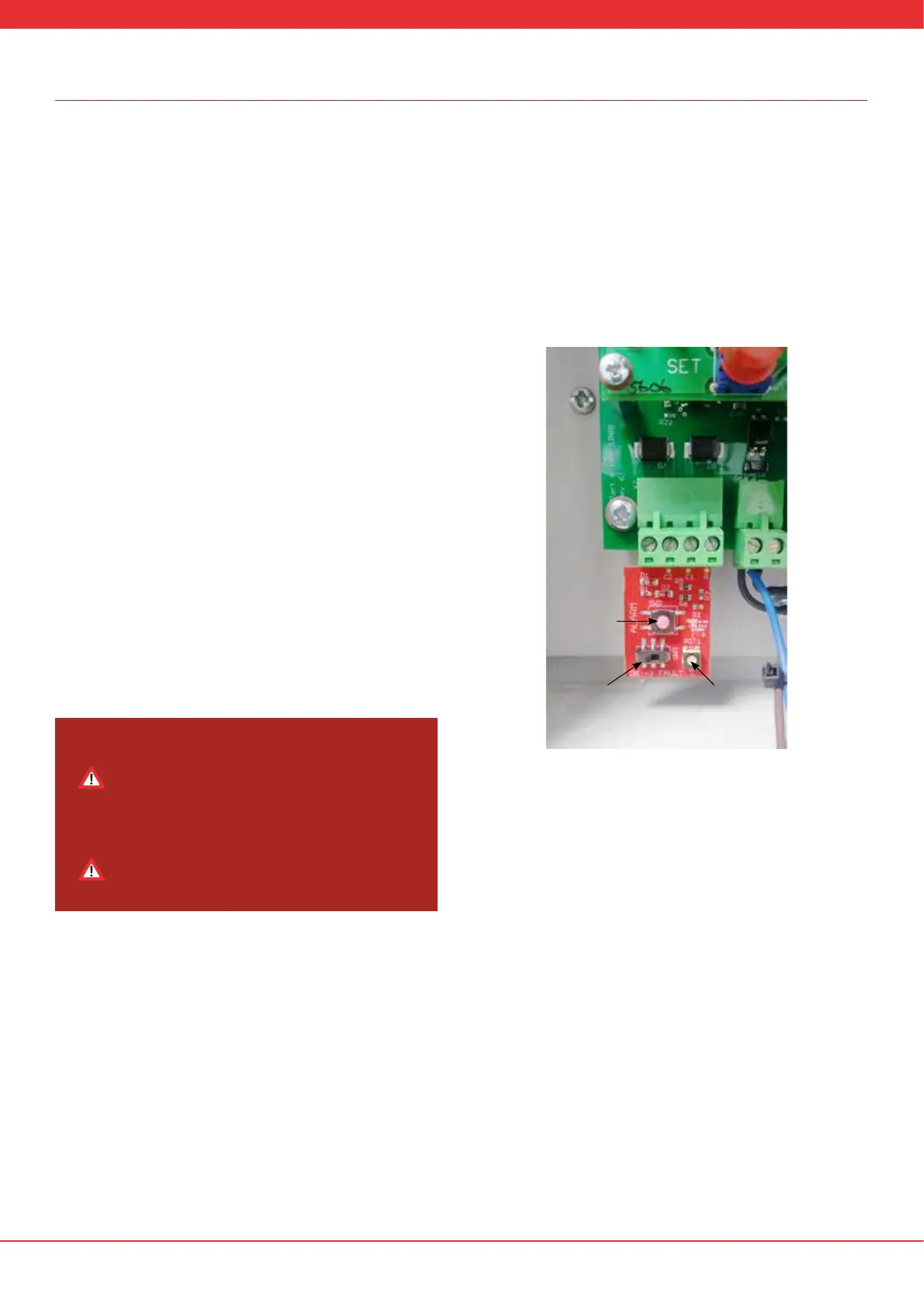
To use the analogue test board rst disconnect the sensor cable from
the control unit and connect the board into the sensor cable terminals
as shown in Figure 12. In order to test the control unit, it must be re-
commissioned to simulate a 50m cable length (calibration resistance =
0.84kohms). Press and hold the SET and SELECT buttons on the control
unit for 15s. The screen should return to display step 1 in the section
“Commission”. Select “Yes” and proceed through the commissioning
procedure but enter a calibration resistance of 0.84kohms.
Pressing and holding the Test Alarm Button for between 5s to 10s should
reduce the “Curr:” value to below the “A:” value. When this happens an
alarm should be triggered. Release the Test Alarm Button and press the
SET button to reset the alarm condition.
Toggle the Test Fault Switch to put the system into a fault condition after
approx 5s.
Once testing has been completed, the sensor cable should be
reconnected and the control unit re-commissioned with the original
calibration resistance and alarm values.
Functional testing of the Analogue LHD system
Analogue Linear Heat Detection Cable is restorable up to 125˚C (257˚F)
and should be functionally tested to ensure it is working correctly.
Consideration should be made during installation to make a portion
(between 1% to 3%) of the sensor cable accessible (i.e. within reach)
for future testing. Wherever possible, for functional testing the system
should be set to the lowest action temperature given the ambient
conditions at the time of testing. Using a suitable device heat between
1% and 3% of detection cable up to a maximum of 125˚C (257˚F). Once
the action temperature (including any tolerances) has been reached
the system should alarm. Ensure the action temperature is reset to the
required value before placing the system back into normal operation.
A suitable test kit for heating the sensor cable in order to carry out a
functional test is available from the manufacturer through your supply
partner.
Set the alarm temperature to 54 deg C and proceed through the
remaining steps in the commissioning procedure.
The control unit should show the diagnostics screen as per normal
operation. With the test fault switch in the “OK” position the “Curr:”
value should be 200MΩ +/- 30MΩ. Turn the ambient temperature dial
counterclockwise until the temperature in the bottom left hand of the
display is approximately 25°C. The “A:” value should be below the “Curr:”
value.
Make a note of the existing calibration resistance and
alarm temperature shown on the screen. You will need to
re-enter these values after the control unit test procedure
has completed and you are returning the control unit to
normal operation.
Do not change the three letter code when using the test
board. It is acceptable for the three letter code
entered in the control unit to remain the same during
the test procedure.
Figure 12: Analogue test board installed in control unit
Test Alarm
Button
Test Fault
Switch
Ambient
Temperature
Dial