MEC 2 MICROPROCESSOR ENGINE/GENERATOR CONTROLLER
PM056 Rev 6 05/10/15 Thomson Technology
32
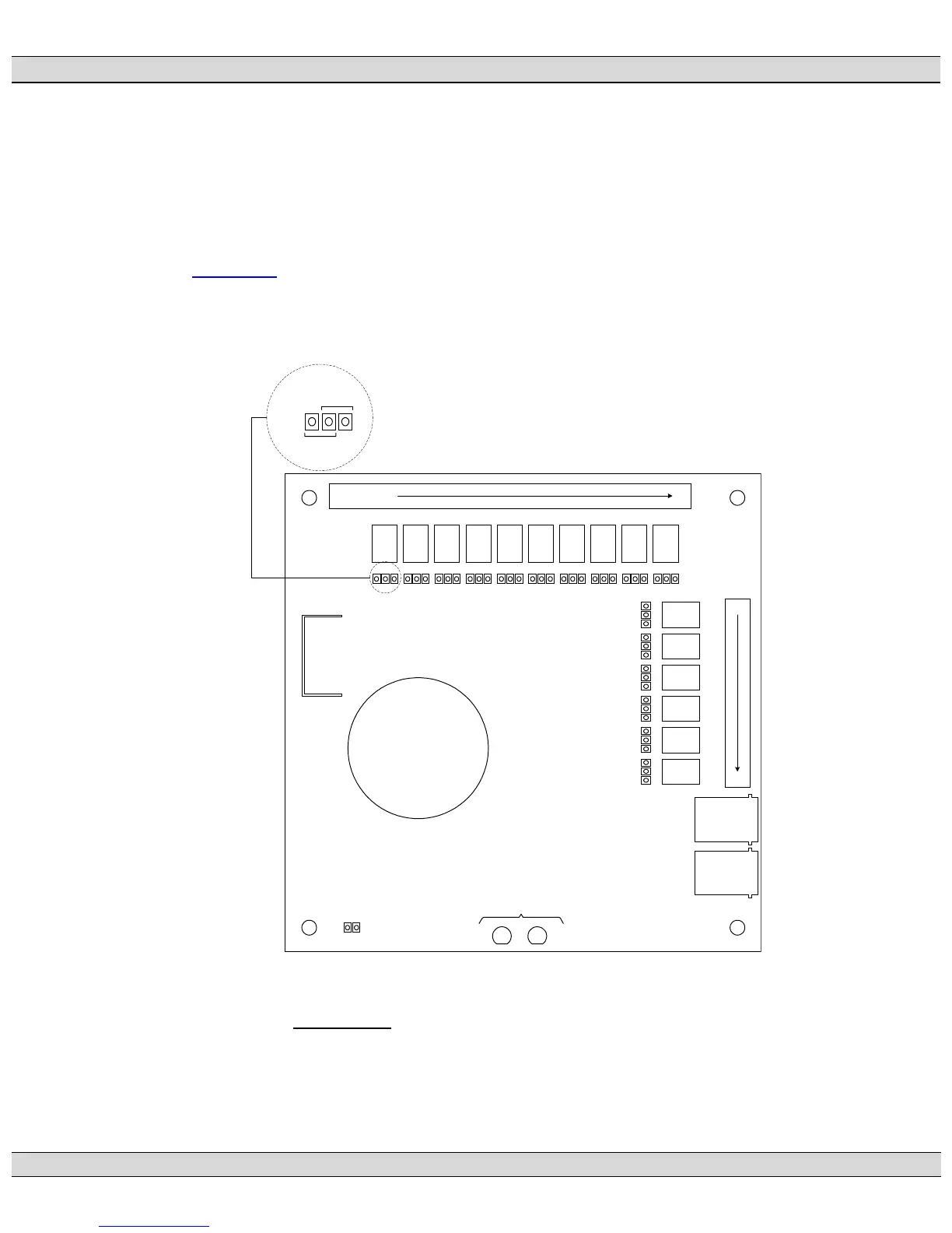
The expansion module outputs are relay contacts that may be individually configured for
normally open or normally closed contact position. Contact configuration is via circuit board
mounted jumper pins and clips. Refer to FIGURE #18 for jumper pin location and configuration
settings. Each output contact is rated maximum 0.5A 120VAC, 1.0A 30Vdc resistive.
Each expansion module also provides one programmable contact for desired control function.
Refer to Section 9.2
of this manual for programming functions and procedures for the
programmable contact feature.
Note: The communication cable between the MEC 2 and the expansion module must be
ordered separately.
G:\ENGINEER\PRODUCTS\MEC2\MEC2_12.VSD
TB1
B+ B- GRD 1 20
K10K9K8K7K6K5K4K3K2K1
21
32
RJ45
(IN)
RJ45
(OUT)
DIAGNOSTIC LED'S
K11
K12
K13
K14
K15
K16
OFF - STANDARD C282/NFPA FAULTS
J1
J2
JMP1 JMP2 JMP3 JMP4 JMP5 JMP6 JMP7 JMP8 JMP9 JMP10
JMP11
JMP12
JMP13
JMP14
JMP15
JMP16
JMP 17
JMP FOR
NORMALLY
OPEN CONTACT
JMP FOR NORMALLY
CLOSED CONTACT
JMP
1-10,
16
FIGURE #14
: MEC 2 EXPANSION OUTPUT MODULE
PRINTED CIRCUIT BOARD LAYOUT
 Loading...


