MEC 2 MICROPROCESSOR ENGINE/GENERATOR CONTROLLER
PM056 Rev 6 05/10/15 Thomson Technology
33
Diagnostic LED’s are provided on each expansion module as shown in FIGURE #13. Their
functions are described as follows:
WATCHDOG - This LED flashes on and off at a very high rate which indicates that the expansion
module microprocessor is functioning normally.
MESSAGE - This LED flashes on and off at irregular intervals which indicates that the expansion
module is correctly receiving all data messages from the MEC 2.
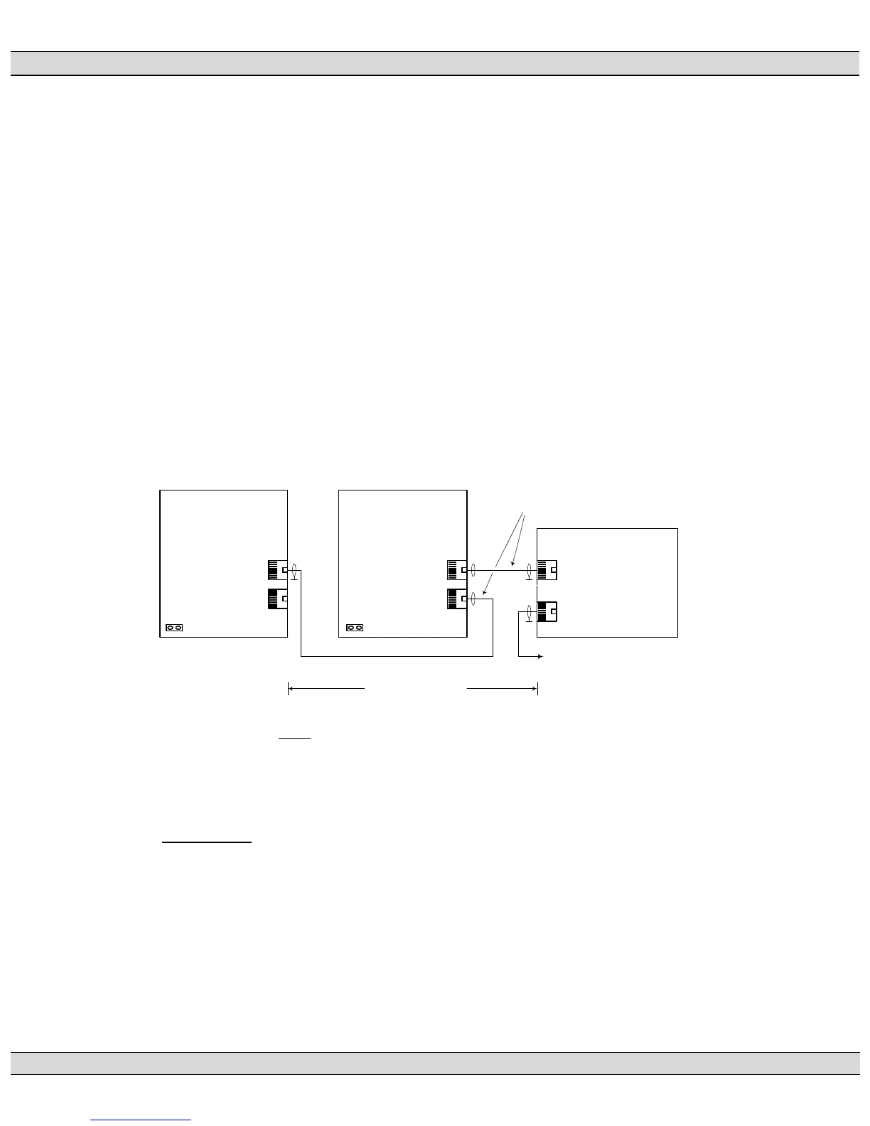
Two expansion modules may be connected to a single MEC 2 controller to provide additional
output contacts. Two modules are interconnected together using a single communication cable
to the MEC 2 controller. Refer to FIGURE #15 for interconnection details. The first expansion
module addresses standard C282/NFPA110 MEC 2 fault circuits
1
and the second expansion
module addresses all additional fault circuits. To select which faults are addressed by each
expansion module, jumper pins and clips are provided on the circuit boards. Refer to FIGURE
#16 for jumper pin location and configuration settings.
1
C282 or NFPA 110 standard faults exclude analog faults Over/Under voltage, Over/Under Frequency, Overcurrent, spare digital inputs #5-#12 and
programmable output #6 (i.e. must specify second expansion module to obtain contacts for these faults).
GRD
GRD
GRD
G:\ENGINEER\PRODUCTS\MEC20\MEC20_17.VSD
MEC 20
Engine
Controller
J7
J6
Expansion
Module #1
(C282/NFPA Standard
Fault Circuits)
Expansion
Module #2
(Additional Fault Circuits)
J17 offJ17 on
To remote
communication
system (optional)
8 conductor Shielded
Cable c/w RJ45 connectors
300M (~1000')
maximum cable
length
FIGURE #15
MEC 2 EXPANSION MODULE INTERCONNECTION DIAGRAM
 Loading...


