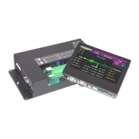
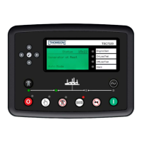
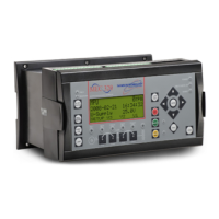
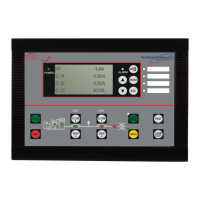
TSC 80e TRANSFER SWITCH CONTROLLER
PM091 Rev 0 09/01/21 Thomson Technology
38
4.6.5.2.TSC 80e UNDER VOLTAGE SETPOINTS WITH NON-STANDARD
SYSTEM VOLTAGES
When the Transfer Switch & TSC 80e transfer controller is applied to non-
standard system voltages, the TSC 80e under voltage software setting
percentages will not correspond to the correct voltage drop out setting.
To obtain the correct drop-out voltages using non-standard system voltages,
the TSC 80e software under voltage setpoints need to have an offset
percentage adjustment with the corresponding voltage software settings.
For non-standard system voltages, the following formula can be used:
A) Desired Drop-out Voltage= Drop-out % x System Voltage
B) TSC 80e UNDER VOLTAGE Setting = (Desired Drop-out voltage x 100)
TSC 80e System Voltage Setting
Example: for 200V system, 85% of 200V= .85 x 200V= 170V
TSC 80e software Setting = (170 x 100)
208
TSC 80e Software Setting = 82%
NOTE
The TSC 80e System Voltage Setting in Software must be set
to be equal to the nominal system voltage level or the next
highest setting available (e.g. 200V system voltage must use
208V jumper setting).
4.6.5.3.PT Ratio
The TSC 80e controller can be programmed in software to display correct
Utility or Generator system line voltage when external Potential Transformers
are utilized on the voltage sensing inputs. Potential Transformers are typically
applied when 3 phase 3 wire system voltage are only available. This menu has
a programmable range of PT ratios from 1.0 to 25.0. Example: for use with
480:120 potential transformers, program ratio of 4.0. To offset minor output
voltage variances of potential transformers used, PT ratio can be programmed
slightly higher or lower using the “tenths” digit. TSC 80e controllers utilizing
direct connected voltage sensing (i.e. without PTs) are to be programmed as
setting “1.0”.
 Loading...
