TSC 80e TRANSFER SWITCH CONTROLLER
PM091 Rev 0 09/01/21 Thomson Technology
3
system voltage. If the transfer switch requires reconfiguring, the TSC80e controller will
require re-programming as well.
WARNING
Failure to confirm and match transfer
switch voltage with the system voltage
could cause serious equipment damage.
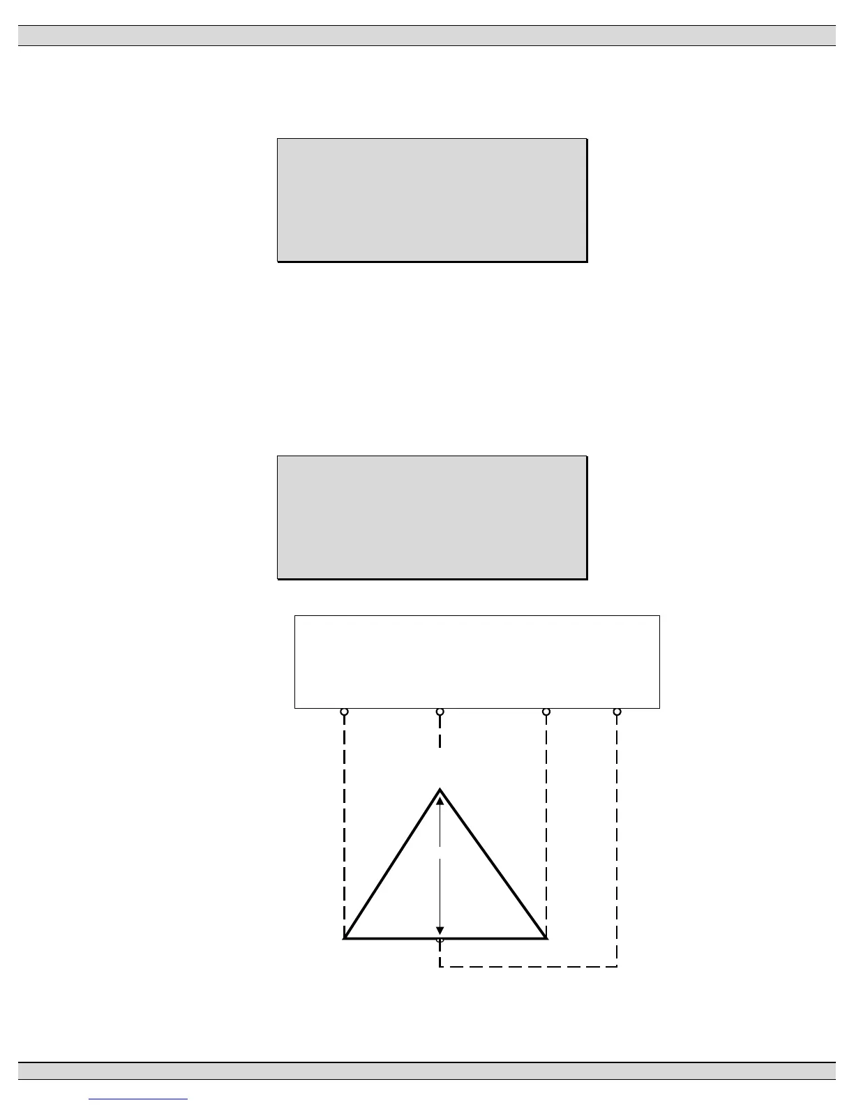
1.3.2. SYSTEM PHASING - HIGH LEG DELTA SYSTEMS
When the transfer switch is connected to a 3-phase 4-wire delta systems, the “High”
leg (Phase B, colored Orange), must be connected to Phase B of the Utility and/or
Generator supply. This will ensure the ATS control power, which is internally
connected between Phase A and Neutral is maintained at 120VAC. Refer to figure
below for further details.
WARNING
Failure to match correct system phasing
will result in serious damage to the
TSC 80e controller.
208V
B
(O range)
(High Leg)
C
(Yellow)
A
(R ed)
N
(W hite)
PH A
(UA)
Automatic Transfer
Switch (Utility Supply)
PH B
(UB)
PH C
(UC)
Neural
(N)
120V 120V
240V 240V