63
Appendix A Rear Panel Connector Pinout Detail
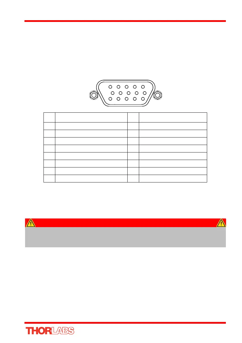
A.1 Rear Panel Motor Control Connector
The ‘Motor’ connector provides connection to the DC servo motor actuator. The pin
functions are detailed in Fig. A.1
* For third part actuators, the action of the limit switch on contact (i.e. switch open or
switch close) is set in the settings panel, see Section 6.3.2.
Fig. A.1 MOTOR I/O Connector Pin Identification
Please contact tech support for details on use with Thorlabs legacy Z6 series DC
Servo Motors.
Pin Description Pin Description
1 Ground 9 Ident In
2 Forward Limit Switch* 10 5V Encoder Supply
3 Reverse Limit Switch* 11 Encoder Channel A
4 Not Connected 12 Not Connected
5 Motor - 13 Encoder Channel B
6 Not Connected 14 Not Connected
7 Motor + 15 Not Connected
8 Not Connected
Caution
DO NOT connect a motor actuator while the K-Cube is powered up.
Only use motor drive cables supplied by Thorlabs, other cables may have
incompatible wiring.