Rev E TR-220 90 008 088-1
2-4
FIG
#
Control, Indicator, or
Connector
(Table 2-2) FUNCTION
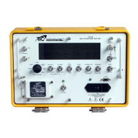
1 SUM Antenna Port
Provides Connection to the Directional Antenna Sum Connector and the
optional TAP-135 Antenna Coupler.
2 DIFF Antenna Port Provides Connection to the Directional Antenna Diff Connector
3 Data Display Window
Alpha/Numeric display (2 lines/20 characters) providing operational
instructions, error messages, scenario progress, and test results.
4 UUT FUNCTION Switch
Provides access to Test Set Menus and Modes.
SETUP- Set Antenna Gain, T/S Distance, TCAS Scenario Selection, Altitude,
Velocity, and Vertical Speed and Distance, Power display (watts or dBm),
Cable Loss, Mode S address, and Latitude and Longitude for ADS-B
Functions.
XPDR- Access ATCRBS and MODE S Transponder test menus.
TCAS- Access TCAS intruder menus.
ADS-B TX- Select ADS-B Transmitter Results.
ADS-B RX- Select ADS-B, and TIS Functions.
DME- Access DME Test menus.
DME- Allows selection of DME Channels. Selectable from 108.0 MHZ in 50
KHz steps. Used in conjunction with UP/FWD – DOWN/REV switch.
TCAS- Set Intruder altitude offset from 99,900’ to 50,200’ in 100’ inc/ 50,175’
to -9000’ in 25‘ increments. Default is 0’. Used in conjunction with UP/FWD –
DOWN/REV switch.
5
CHN/ALT, DIST, VERT
SPEED Switch
TCAS- Intruder vertical speed in “feet per minute” (fpm) adjustable in 100’
increments from +7500’ to -7500’. Used in conjunction with UP/FWD –
DOWN/REV switch.
6
UP/FWD, DOWN/REV
Switch
Used in conjunction with CHN/ALT, DIST, VERT SPEED switch to vary
parameters. Also used to set antenna gain and Test Set distance in SETUP
mode.
7
TO/START – FROM/STOP
Switch
Start and Stop TCAS Intruder scenarios and change DME To/From
parameters.
8 IDENT Switch Initiates a SPI Pulse for verification of transponder IDENT function.
9
ATCRBS/AIR, MODE S /GND
INTRUDER Switch
Selects TCAS Intruder Type (MODE S or ATCRBS), and Air or Ground
position.
10
INCREASE/DECREASE
VELOCITY
Sets TCAS Intruder and DME speed velocities. Also utilized for ADS-B TX/RX
Functions.
11 Direct Connect Port
For direct connection to a Transponder. Provides accurate RF Power,
frequency and sensitivity measurements.
12
MOM/BACK LIGHT/ON
Switch
Activates display backlighting either “ON” or momentarily.
13
AUTO/TEST/MANUAL
Switch
Allows the operator to select an Automatic Sequence of Transponder tests or
a Manual sequence. Initiates TCAS and DME scenarios. Hold AUTO key
when Test Set power is turned “ON” to select CW operation. Use AUTO and
MANUAL to advance through EHS and ADS-B tests.
14 STORE connector RS-232 port for download of stored data to a PC.
15 Test Set charging indicator Indicates to operator that the Test Set Batteries are charging
16 AC Power Panel
1. Provides connection to a 115 or 220 VAC power source.
2. AC “ON” / “OFF” switch for battery charging.
3. Fuse Cartridge.
17
TEST SET ON/OFF
Switch
Turns Test Set “ON” and “OFF”.
18 Power ON “LED” Indicates to the operator that the Test Set is “ON”.