Rev E TR-220 90 008 088-1
2-10
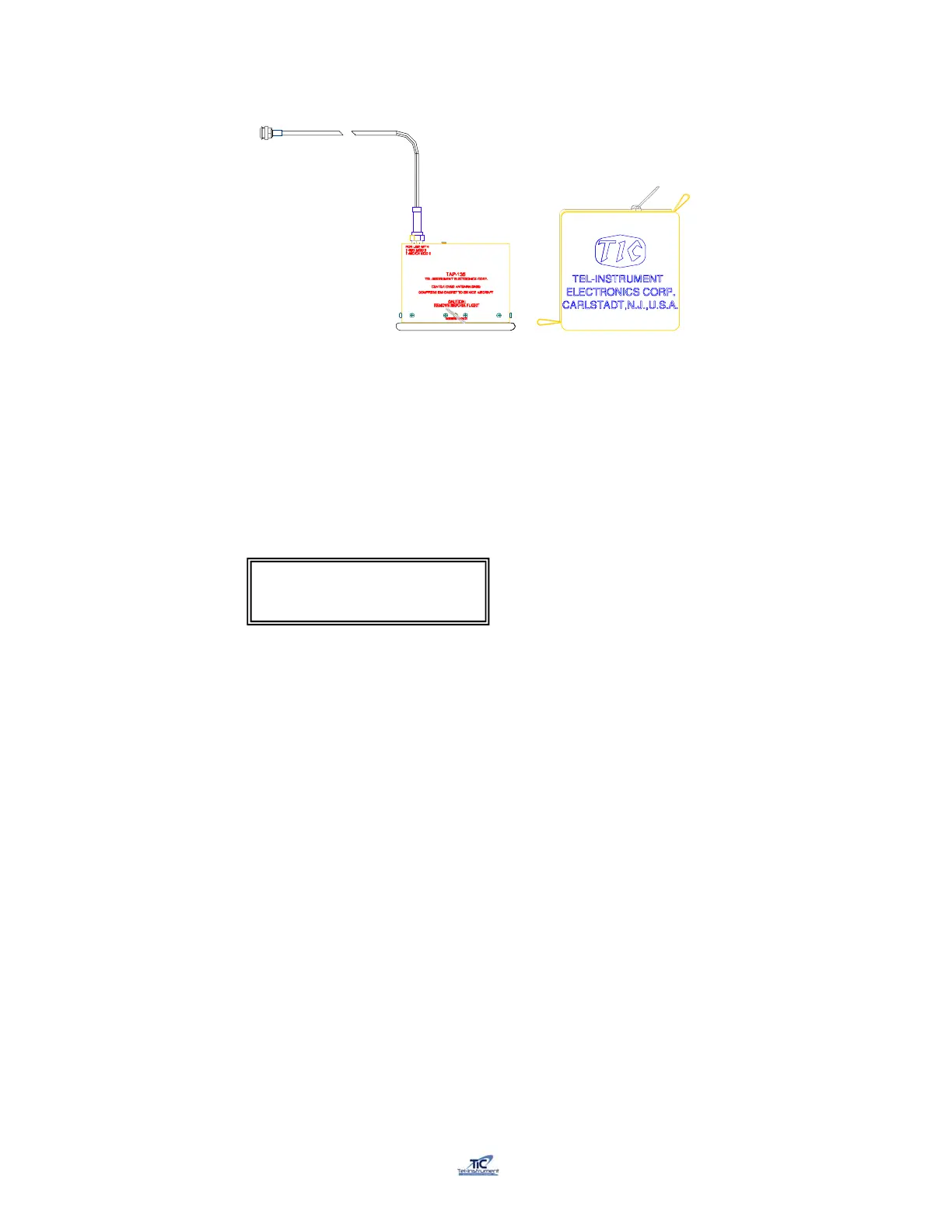
TAP-200 Coupler
Figure 2-5
1. Connect the TAP-200 Cable to the TR-220 antenna SUM port.
2. Turn the test set ON by toggling the ON/OFF switch Up and turn
the UUT FUNCTION switch to the SETUP position. Scroll to the Antenna
Selection screen using the AUTO/MANUAL switch.
3. Use the UP/FWD-DOWN/REV switch to select TAP.
4. To install the coupler, pull the ring, which separates the spring-loaded clamp, and
slide the coupler over the blade antenna. Ensure that the EMI gasket of the
coupler is flush with the aircraft skin and that the coupler is centered over the
antenna. Release the ring (fig 2-6).
5. Ensure that the coupler is centered over the antenna to be tested.
6. Due to the availability of numerous styles of antennas, slight adjust of the
Coupler may be necessary to receive accurate measurements. If incorrect
readings occur, re-position and ensure a snug fit on the antenna. Move the TAP-
200 forward or back and double check a firm and snug seal on the aircraft
surface (fig 2-7).
7. An accurate adjust of the couplers can be accomplished by advancing to the
Manual Mode of tests POWER, RECEIVER, FREQ test page and adjusting the
coupler for the maximum power out. Once adjusted, the operator can then restart
the appropriate series of tests ensuring accurate results.
Antenna: TAP
Chg:Up/Dn Cont:AUTO