TiLite
®
OM000007 - Rev. B
57
Backpost
3. Remove the camber tube.
4. Install the new camber tube, making sure the
distance from the outside edge of the camber clamp
to the end of the camber tube is identical on each
side of the chair.
5. Securely tighten both Allen Screws.
6. Reinstall the rear wheels.
7. Check the toe-in/toe-out and adjust as needed.
Adjusting the Center of Gravity
(TR, YR and BB)
Tools Needed:
• 3/16” Allen Wrench
• Ruler
1. Remove the rear wheels.
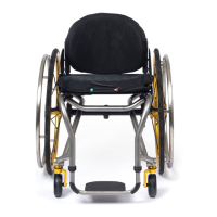
2. Loosen, but do not remove, the six Allen Screws
(three on each side of the chair) that secure the axle
clamps and camber tube mounts to the frame. See
Figure 67.
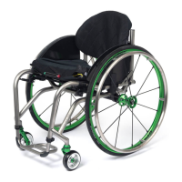
3. Simultaneously slide both camber tube clamping
assemblies forward or rearward along the frame
until they are positioned in the desired location. Use
a ruler to ensure both camber tube clamping
assemblies are the same distance from the back
post (measured from the back post to the top of the
clamping assembly). See Figure 68.
4. Securely tighten the six Allen Screws that secure
the axle clamps and camber tube mounts to the
frame.
5. Reinstall the rear wheels.
6. Check the toe-in/toe-out and adjust as needed.
Replacing the Camber Tube
(TR, YR and BB)
Tools Needed:
• 3/16” Allen Wrench
• Ruler
1. Remove the rear wheels.
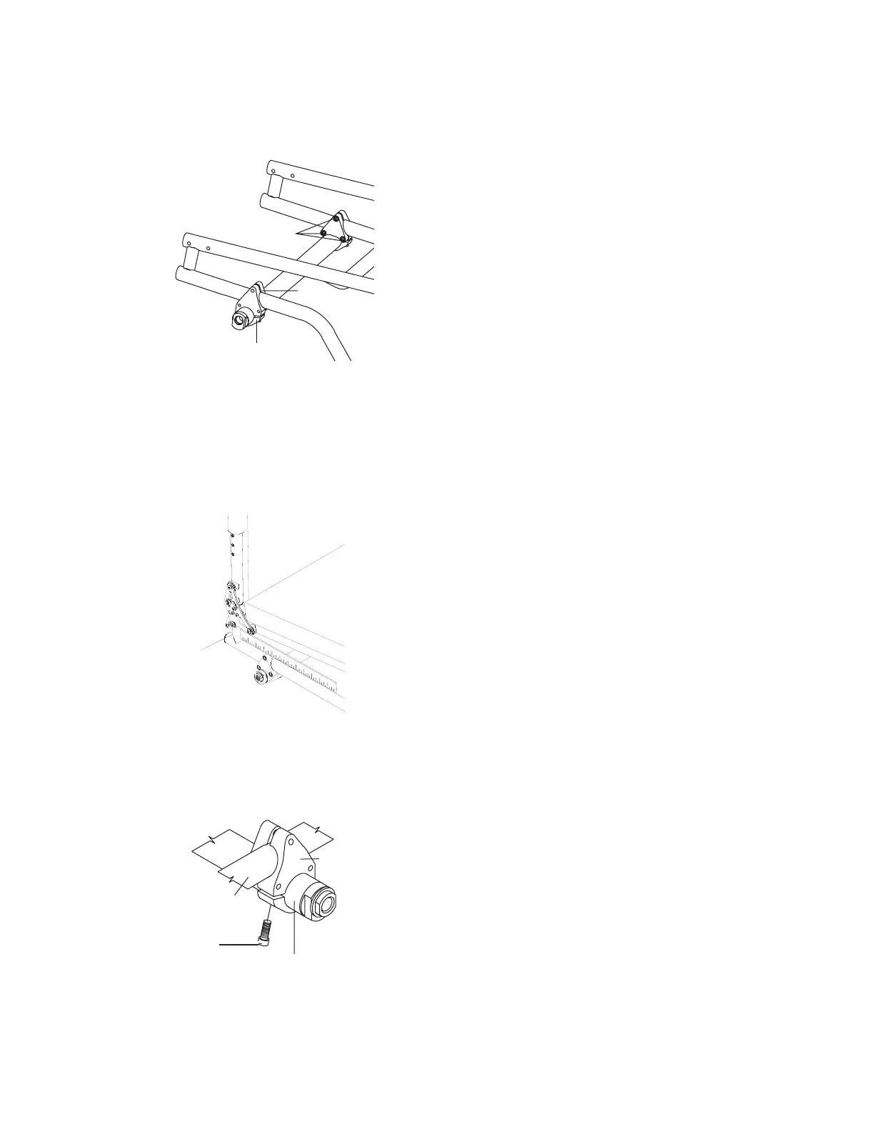
2. Loosen, but do not remove, the Allen Screw that
secures the camber tube to each camber tube
mount. See Figure 69.
3. Remove the camber tube.
4. Install the new camber tube, making sure the
distance from the outside edge of the camber tube
mount to the end of the camber tube is identical on
each side of the chair.
5. Securely tighten both Allen Screws.
6. Reinstall the rear wheels.
7. Check the toe-in/toe-out and adjust as needed.
Figure 67
Adjusting the Center of Gravity of the TR, YR
and BB
Allen Screws
Axle
Clamp
Camber
Tube
Mount
Frame
Camber Tube
Socket Head
Cap Screw
Camber Tube
Mount
Figure 69
Replacing Camber Tube on TR, YR and BB
Figure 68
Adjusting the Center of Gravity of the TR, YR and
BB
Backpost
Allen
Screw
 Loading...