TiLite
®
OM000007 - Rev. B
64
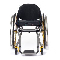
Figure 80
Adjusting Skewer Handle Tension
Unlocked
Position
Locked Position
Allen Screw
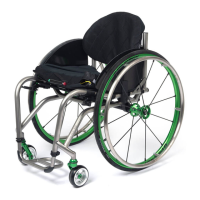
Figure 81
Adjustable Camber System
Allen Screws
Retaining Plate
Rear View
Adjustable Camber
Mounting Plate
Skewers
Front View
Allen Screw
Adjustable Camber System
(TR and YR)
Adjusting the Skewer Handle Tension
1. Release the handle on the skewer to the unlocked
position. See Figure 80.
2. Loosen or tighten the Allen Screw on the end of the
skewer.
3. Return the handle of the skewer to the locked
position.
Changing the Camber
Tools Needed:
• 3/8” Allen Wrench
1. Remove the rear wheels and turn your chair upside
down.
2. Unlock all four skewers. See Figure 81.
3. Remove the two Allen Screws and the two retaining
plates from the rear side of the adjustable camber
mounting plate.
4. Remove all four skewers from adjustable camber
mounting plate.
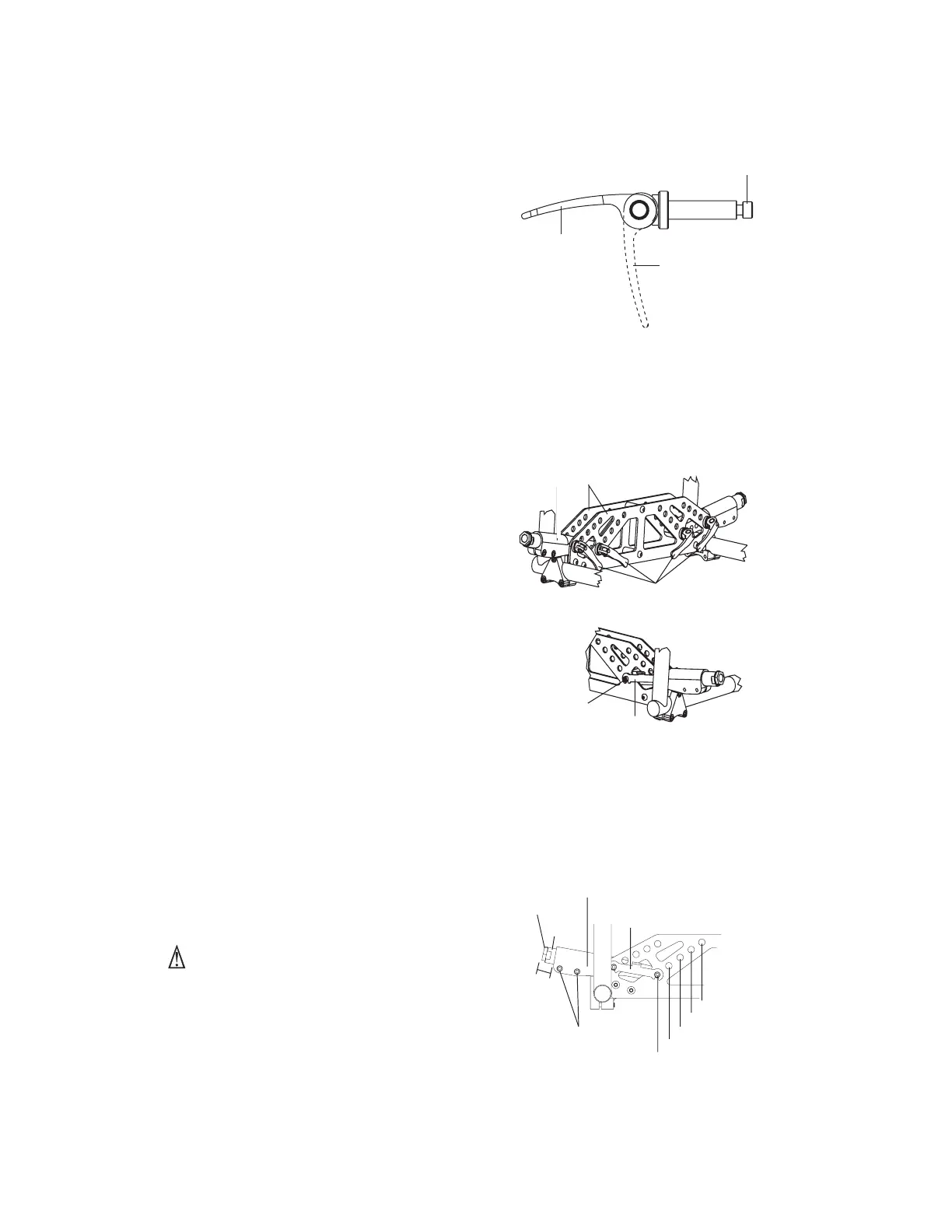
5. Using Figure 82, determine the placement of the
retaining plate and skewers that will achieve your
desired camber.
6. Reposition the axle sleeve mounts to the desired
camber position, making sure to align the holes in
the axle sleeve mount with the holes on the front
and rear adjustable camber mounting plates. See
Figure 82.
7. Reinsert the skewers through the adjustable camber
mounting plates and the axle sleeve mounts.
8. Reinstall the retaining plates and Allen Screws at
the rear side of the adjustable camber mounting.
9. Return the handles of all four skewers to the locked
position.
10.Reinstall the rear wheels and turn the chair right
side up.
11. Check the toe-in/toe-out and adjust as needed.
A
dd
dd
djusting Rear Wheel Spacing
Tools Needed:
• 3/16” Allen Wrench
WARNING
Do not extend the camber plug more than 1-1/2” out of
the axle sleeve mount. If more than 1-1/2” of the
camber plug is outside of the axle sleeve mount, the
camber plug could disengage from the axle sleeve
mount while you are using the chair. If you ignore this
Warning, you may fall, tip over or lose control of the
wheelchair and seriously injure yourself or others or
damage the wheelchair.
1. Remove the rear wheels.
Figure 82
Camber Settings
1.5” Max
Distance
Axle Sleeve Mount
Camber
Plug
Axle Sleeve
9º
Retaining Plate
12º
Allen Screws
3º
6º
0º
 Loading...