Titan Implement, LLC 33 1200-1600 Series Rotary Cutters
(423) 334-0012 August 2016
Note: The rotary cutter will not operate on tractors
equipped with a 1000 RPM 21-spline or 1000
RPM 20-spline, 1-3/4” shaft.
Refer to the tractor owner’s manual for instructions to
change PTO speeds on models that operate at more
than one speed.
If operating an older model tractor where the tractor’s
transmission and PTO utilize one master clutch,
an over-running clutch must be used between the
PTO output shaft and the driveline of the mower. An
authorized tractor dealer can provide the over-running
clutch and its installation, if needed.
DO NOT use a PTO adapter to attach a non-matching
implement driveline to a tractor PTO. Use of an adapter
can double the operating speed of the implement,
resulting in excessive vibration, thrown objects, and
blade and implement failure. Adapter use will also
change the working length of the driveline exposing
unshielded driveline areas. Serious bodily injury and/or
equipment failure can result from using a PTO adapter.
Consult an authorized dealer for assistance if the
implement driveline does not match the Tractor PTO.
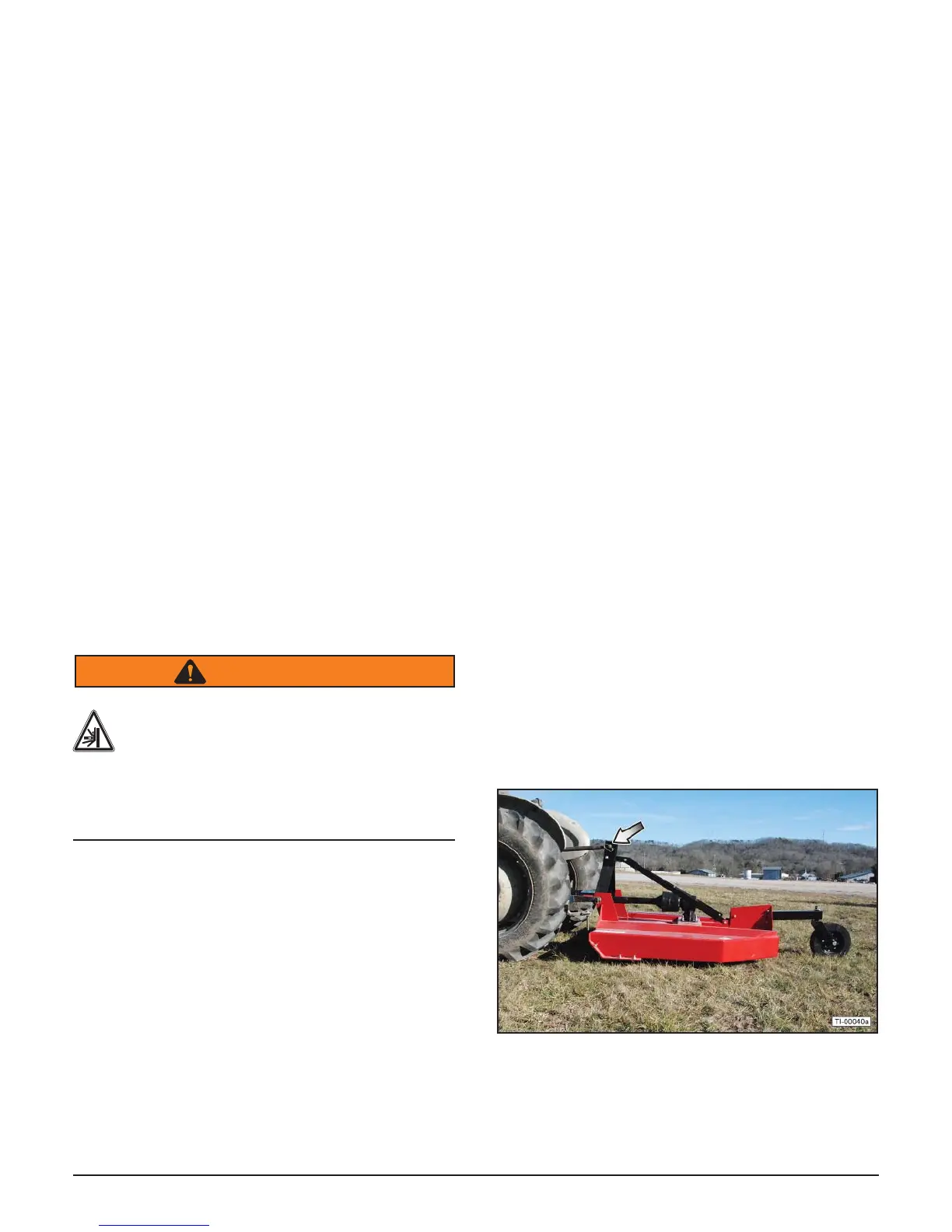
6.3 Attaching to Tractor
Use caution when connecting the rotary cutter to the
tractor. The rotary cutter should be securely resting at
ground level or setting on blocks. Keep hands and feet
from under the deck and clear of pinch points between
the tractor hitch arms and rotary cutter hitch pins.
WARNING
Crush Hazard
Crush hazard between hitch and implement.
Do not allow anyone to stand between the
hitch and implement during hook-up
operations. Never operate the hydraulic
3-point lift controls while someone is directly
behind the tractor.
1. Shorten or remove the tractor drawbar to avoid
interference when raising and lowering the rotary
cutter.
2. Board the tractor and start the engine. Position the
tractor with the 3-point lift arms positioned at the
same height and to the outside of the rotary cutter
hitch pins.
Note: Set the 3-point lift control to “Position Control”
so that the lift arms maintain a constant height
when attaching the rotary cutter. See the tractor
Operator’s Manual for correct settings when
attaching 3-point equipment.
3. Turn off the tractor engine and dismount.
4. One lift arm at a time, insert hitch pin through the lift
arm holes and install retaining pin.
5. Walk around to the opposite side and repeat the
procedure for remaining lift arm and hitch pin.
6. Extend or retract 3-point top link to align its end hole
with the holes of the rotary cutter’s top link. Insert
the top link hitch pin and insert the retaining pin into
the hitch pin.
7. Adjust any lower link check chains, guide blocks,
or sway blocks to prevent the rotary cutter from
swaying side-to-side and possible contact with the
tractor rear tires.
6.4 Detaching from Tractor
1. Move the rotary cutter to a level storage location
and lower it to the ground or onto blocks. Park the
tractor, place the transmission in park or neutral,
and apply the parking brake. Lower the rotary cutter
to the ground, shut down the engine, remove the
key, and wait for all motion to come to a complete
stop before exiting the tractor. Before disconnecting
the rotary cutter, the PTO must be disengaged and
blade rotation at a complete stop.
2. Make sure the rotary cutter is resting securely
on the ground or blocks before attempting to
disconnect it from the tractor. Use extreme care to
keep feet and hands from under the rotary cutter
and clear of any pinch points caused by the tractor
hitch arms and rotary cutter hitch pins.
3. Extend the tractor 3-point hitch top link to remove
tension on the top link hitch pin. When the pin is
loose and easy to rotate, remove the pin from the
rotary cutter.