Titan Implement, LLC 43 1200-1600 Series Rotary Cutters
(423) 334-0012 August 2016
9.5.3 Blade Sharpening
CAUTION
Sharp Object Hazard
The grinder may catch on the blade during
sharpening, propelling it forcefully. To
prevent the possibility of serious injury, make sure
blades are secured against movement while
sharpening.
When sharpening blades, always sharpen both blades
at the same time and grind the same amount on each
blade to maintain balance. Unbalanced blades will
cause excessive vibration, which can damage gearbox
bearings. Vibration may also cause structural cracks
to the rotary cutter. Follow the original sharpening
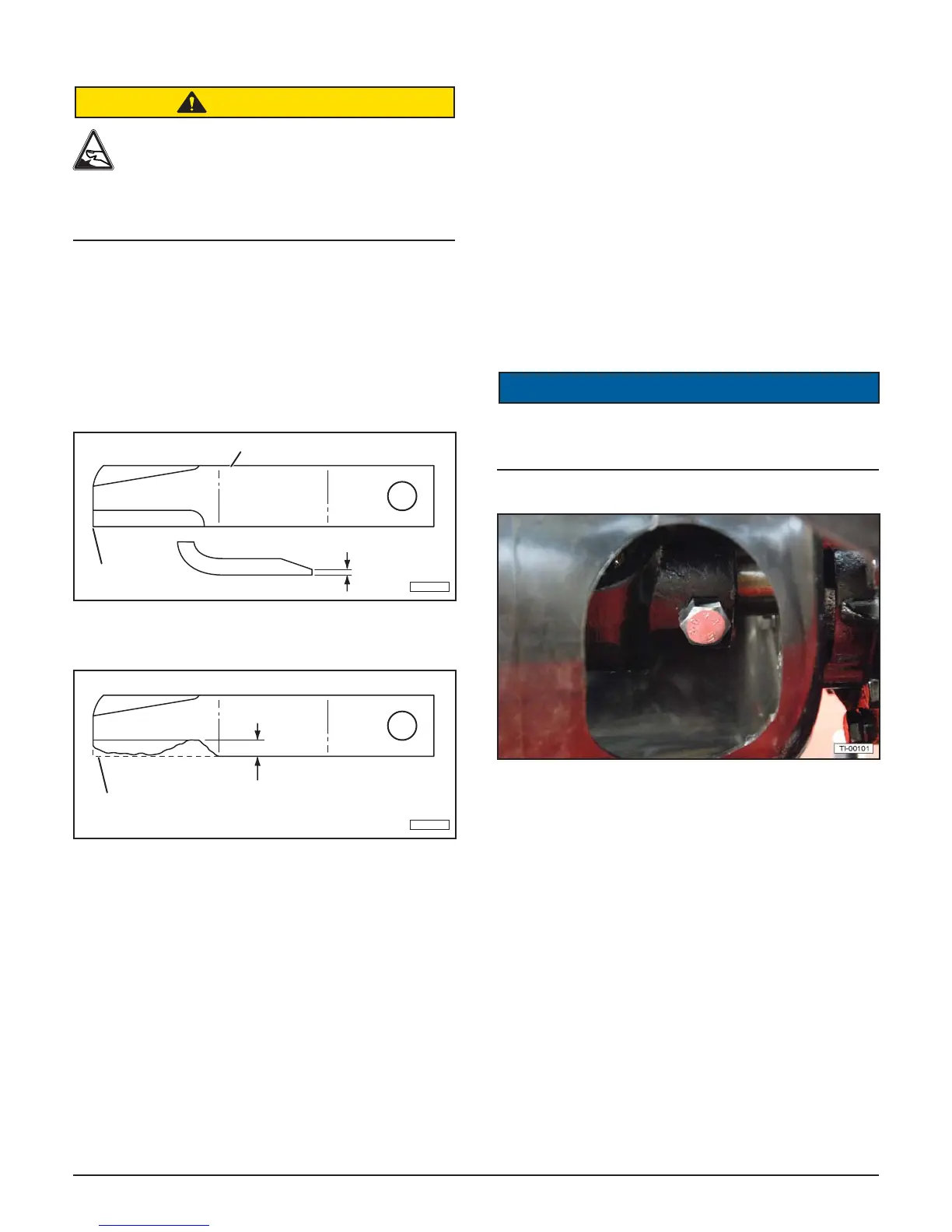
pattern. Do not sharpen blades to a razor edge, leave
a 1/16” blunt edge. Do not sharpen the back side of
the blade. Do not heat and pound out the edge.
1/16”
FOLLOW ORIGINAL PATTERN
MAINTAIN
CORNER
TI-00064
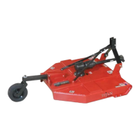
Replace the blades when worn more than 1/2” from the
original edge. Always replace blades in pairs.
ORIGINAL
BLADE EDGE
1/2” MAXIMUM
TI-00063
9.6 Blade Carrier Removal
1. Remove the cotter pin and loosen the castle nut on
the gearbox shaft. Do not remove the nut until the
blade carrier is loosened.
2. Use a suitable two jaw gear puller to pull the carrier
off the tapered gearbox shaft.
3. If a gear puller is not available, insert a bar through
the blade bolt access hole with the end against the
blade carrier. Strike the opposite end of the bar
sharply. Rotate the blade carrier 180 degrees and
repeat until the carrier breaks loose.
4. Remove the castle nut and the blade carrier.
9.7 Blade Carrier Installation
1. Clean the splines on both the blade carrier and the
output shaft.
2. Position the carrier on the gearbox output shaft and
install the castle nut. Tighten the nut to a minimum
450 ft. lbs.
3. Strike the carrier near the hub several times with
a heavy hammer to seat the hub. Use care not to
strike the nut or the end of the shaft.
4. Retighten the nut to 700 ft. lbs.
5. Install the cotter pin and spread the tangs.
9.8 Shear Bolt Replacement (If Equipped)
NOTICE
Always use an approved Grade 2 shear bolt as a
replacement part. Using a hardened bolt or shear pin
may result in damage to driveline or gearbox.
1. Open the access covers on the gearbox shield bell.
2. Rotate the driveline to align shear bolt with the
access hole in the gearbox shield. Remove the
damaged shear bolt.
3. Align the holes in the U-joint and shaft.
4. Install shear bolt and secure with lock nut.
5. Close the access covers on the gearbox shield bell.
9.9 Slip Clutch Operational Check
The slip clutch serves as overall protection for the
tractor, driveline, and gearbox. Even though new
clutch assemblies are “run-in” and checked for torque
prior to shipment, re-adjustment may be advisable
if the clutch has been exposed to weather for an
extended period of time. The clutch facing and plates
should be inspected for rust and/or corrosion. After the
rotary cutter has been stored for thirty days or more,
perform the following check: