1200-1600 Series Rotary Cutters 44 Titan Implement, LLC
August 2016 (423) 334-0012
1. Make a trial run in the heaviest operating conditions
expected. If the clutch slips noticeably, tighten the
eight adjusting bolts no more than 1/2 turn between
trial runs until the clutch slippage is reduced.
2. Scribe a mark across the clutch facing. When
subjected to shock loads, a separation of the marks
will assure that the clutch setting is correct.
Note: Check the clutch periodically during the fi rst
hour of operation for excessive heat build-up
due to unexpected slippage.
If the clutch is being rebuilt (new facing and/or plates),
it is necessary to “run-in” these parts prior to fi nal
adjustment. The plates should be thoroughly cleaned
and free of foreign material, as well as being checked
for warping with a straight edge. Warped plates cannot
be adjusted properly and will not hold. To accomplish
the “run-in” after assembly, follow this procedure:
3. Tighten all the adjusting bolts evenly until the clutch
cannot be slipped by hand.
4. With the blade carrier locked in a stationary position,
operate with the PTO at idling speed (approx. 100
RPM), until evidence of heating is noted. Do not
allow the clutch to overheat.
5. Discontinue operation and allow the clutch to
cool completely.
6. After the clutch has cooled, tighten all the adjusting
bolts evenly and proceed with the regular clutch
adjusting procedures as described above.
9.10 Slip Clutch Adjustment
The slip clutch is factory preset to the correct torque
for protecting the implement and tractor: Periodic
adjustment is recommended. Should adjustment be
needed, follow this procedure:
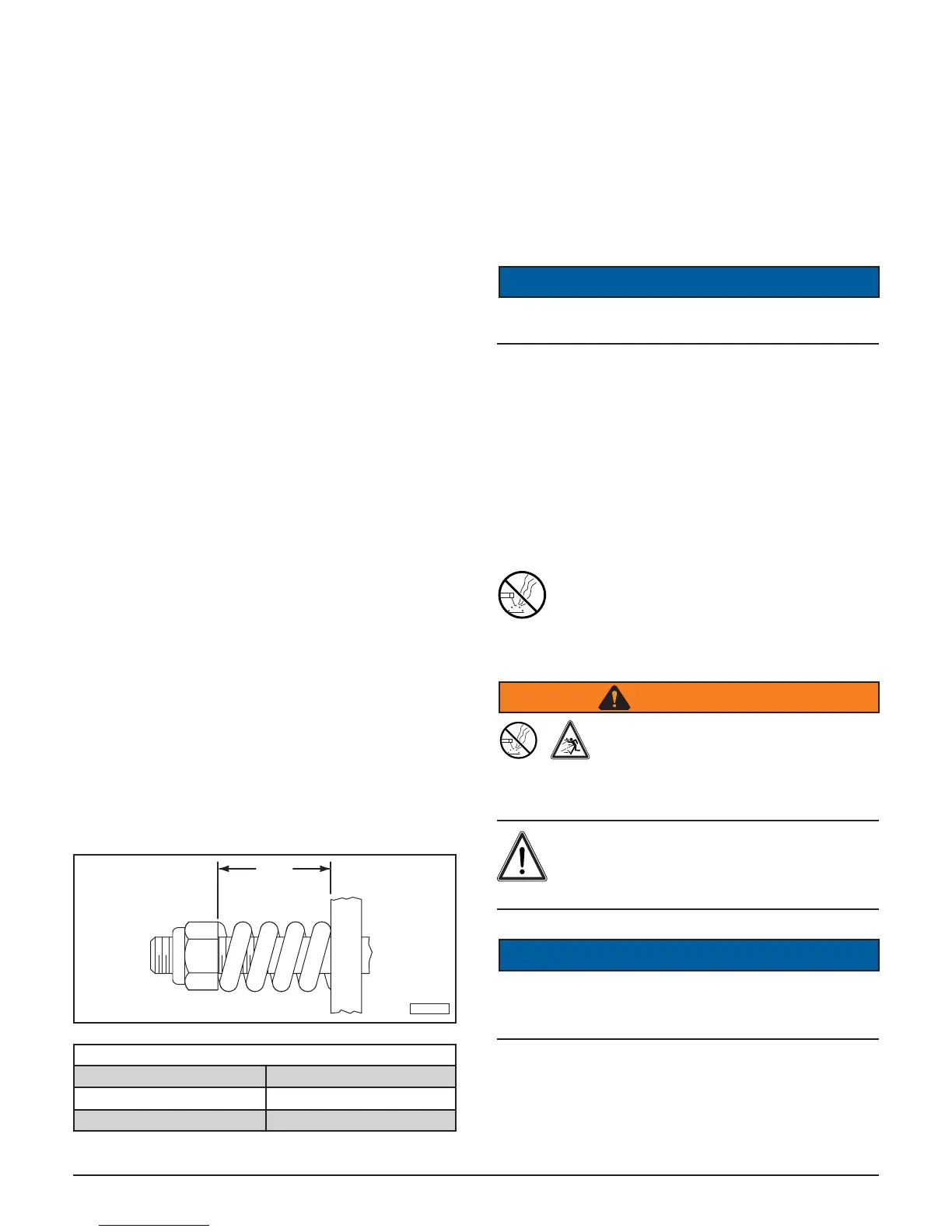
1. Check to be sure all spring lengths are the same.
Initial spring length is shown in the chart.
TI-00102
SEE
CHART
CLUTCH SPRING LENGTH CHART
EG / COMER BONDIOLI & PAVESI
1.27” (32.2mm) 1.15” (29.3mm)
1.28” (32.4mm) 1.12” (28.5mm)
2. If necessary, adjust the nut on any spring that is
unequal. Adjust all eight spring retaining nuts
1/3 of a turn (two fl ats on a nut) and check clutch
slippage.
3. If further adjustment is necessary, adjust in
1/3 turn increments. Adjust only to provide
suffi cient torque to prevent slippage under normal
conditions. Occasional slippage is normal for drive
train protection. If satisfactory results cannot be
obtained, consult your authorized dealer.
NOTICE
Do not overtighten and cause the spring to become
solid, as this will cause shaft failure.
9.11 Bolt Torque Requirements
It is extremely important to apply and maintain proper
torque on all bolts. Use a torque wrench to assure
the proper amount of torque is being applied to the
fastener. For proper bolt torque values, refer to “11.1
Bolt Torque” on page 53.
Start all bolts or nuts by hand to prevent cross
threading.
9.12 Welding Repairs
Before performing any type of welding repair to
the rotary cutter, contact Titan Implement for
approval. Repair welding must be done with
care and with procedures that may be beyond the
capabilities of the ordinary welder.
WARNING
Projectile Hazard
Do not attempt to weld on the blades.
They are hardened and will crack or
otherwise be damaged, causing failure and possible
serious injury or death from thrown blades.
Personal Injury Hazard
Repairs or modifi cations to the rotary cutter
can result in serious injury or death should
these repairs fail.
NOTICE
Anyone performing a welding repair should be certifi ed
in accordance to the American Welding Society (AWS)
standards.