71
WB-RM200 Wall Mounting Bracket for the RM-210.................... 1 (option)
Machine screw M3.5 x 20 (for an electrical box mounting) ......... 2 (supplied with the WB-RM200)
Tapping screw 4 x 25 (for direct wall mounting).......................... 2 (supplied with the WB-RM200)
• Install the RM-200M only in a location
that can structurally support the weight
of the unit and the WB-RM200 bracket.
Doing otherwise may result in the unit
falling down and causing personal injury
and/or property damage.
• Use 2 or more screws to fix the WB-
RM200 to the wall.
WARNING
WB-RM200 Wall
Mounting Bracket
(option)
RM-200M
LINK
Link cable
Notch
1
2
3
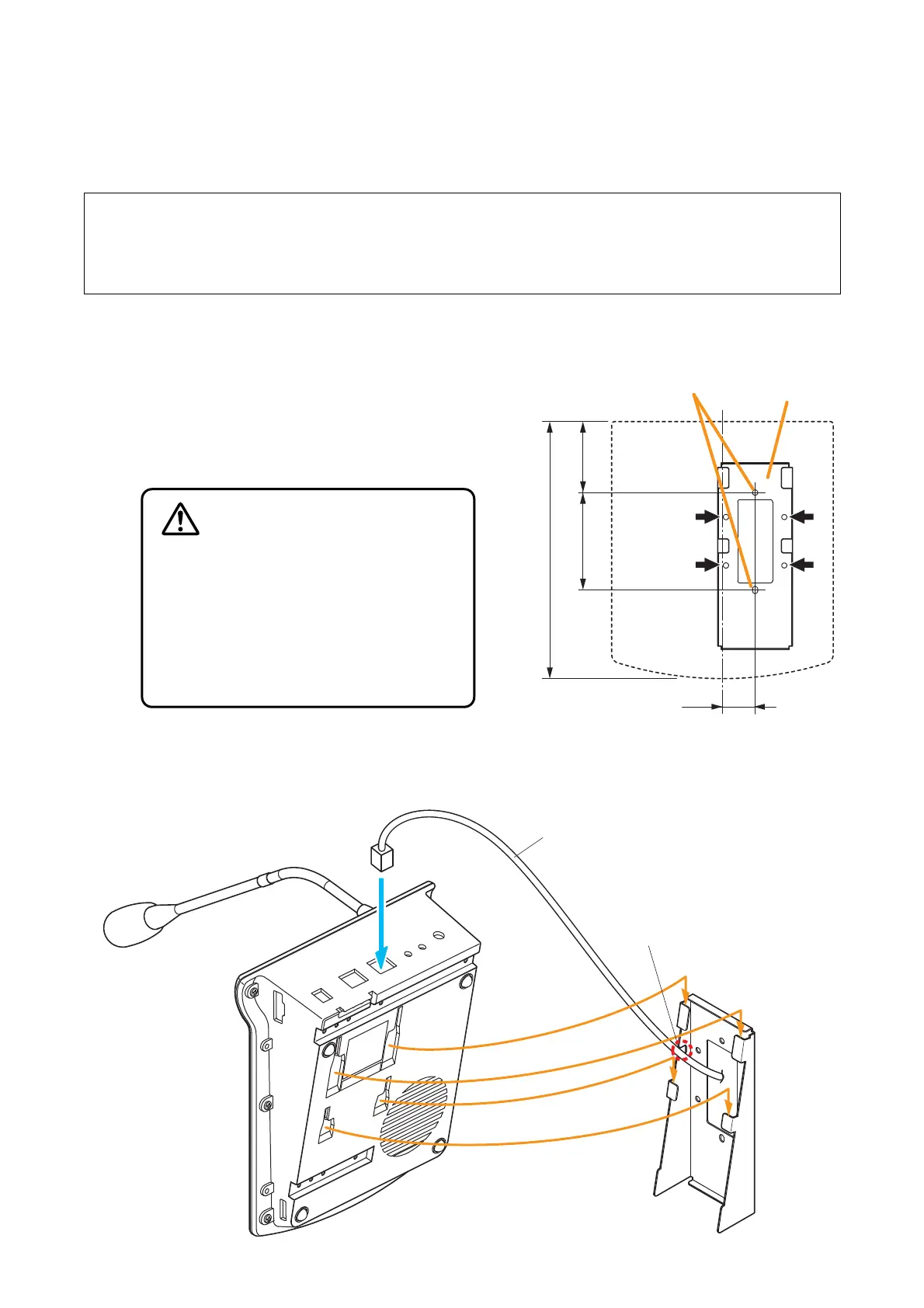
[Positional dimensions of the WB-RM200]
60.883.5
220.3
28
Unit: mm
RM-200M
WB-RM200
(option)
Mounting holes for
an electrical box
Use 4 mounting holes
indicated by arrows to
secure the WB-RM200
to the wall
12.1. Installing the RM-200M on a Wall
To mount the RM-200M on the wall, the following parts are required.
Step 1. Install the optional WB-RM200 bracket on the
wall.
Pull out the link cable through the bracket’s
notch.
As 2 types of supplied screws are available for
electrical box mounting and direct wall mounting,
use appropriate ones for mounting method.
Step 2. Hook the RM-200M’s bottom onto the WM-RM200.
Step 3. Connect the link cable to the RM-200M’s link connector.
12. INSTALLATION