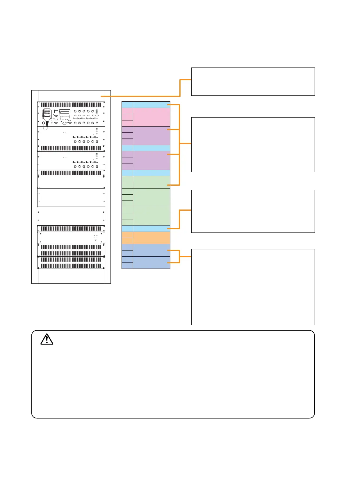
• Mount the power amplifier as high as
possible in the rack.
• Mount a 1U* perforated panel above and
below every 2 units for the VM-3240VA
and VM-3240E.
* 1U size = 44.5 mm (reference size)
Mount a perforated panel above the VX-
2000DS to facilitate its internal fuse
replacement because fuse can be
accessed through the rear most section of
the top panel.
When batteries are installed in the rack,
place them directly below the VX-2000DS
so that they can perform temperature
compensation for the charging voltage.
In this case, use a perforated panel in front
of the rack to avoid excessive temperature
rise around the batteries.
For installing batteries, refer to the
Instruction Manual attached to the VX-
2000DS.
It is recommended that a blower unit be
installed at the uppermost position for
efficient exhaust of inner heated air.
Notes
• Because the VM-3240VA, VM-3240E, and VX-2000DS are heavy, use guide rails (separately prepared) in
the rack to safely mount and securely support the units.
• The perforated panel is recommended in place of space.
Follow the instructions below. Doing otherwise may cause the unit to fall, possibly resulting in personal
injury.
• As the VM amplifiers do not come with rack-mounting screws, prepare locally the screws that are
appropriate for the equipment rack.
• The VM-3240VA and VM-3240E can be mounted in an EIA-Standard equipment rack (3 U* size).
* 3 U size = 133.5 mm (reference size)
• The rack-mounting screws supplied with the units other than the VM amplifiers are dedicated for the
TOA racks. Never use them for any other rack.
CAUTION