4
4-3
4st 60 2019
2. Ignition System
For ignition system, battery ignition system is adopted, and ECU's electronic ignition timing control system controls the
timing to the most suitable state according to current operating conditions.
As engine is started, electric current is generated in the alternator and to charge the battery. Which is input to ECU's
regulator to feed power needed for operations of ignition coil, fuel injector and fuel feed pump (FFP).
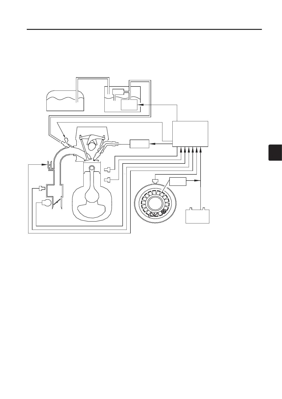
(1) Configuration of Ignition System
Ignition system consists mainly of the following components.
(1) Sensors and switches that transmit engine operating states to ECU.
(2) ECU that performs electronic control.
(3) Ignition coils and spark plugs that operate in accordance with control by ECU.
The following 6 components are included in the sensors and switches of (1).
• Pulser coil Crank position (Crank Position Sensor)
• Throttle Position Sensor (TPS) Throttle opening angle
• Water Temperature Sensor Temperature of ENGINE (Crankcase)
• MAP (Manifold Air Pressure) Sensor Vacuum pressure of intake air
• MAT (Manifold Air Temperature) Sensor Temperature of intake air
• Oil Pressure Switch Reduction of hydraulic pressure
* Integrated MAP (Manifold Pressure) Sensor and MAT (Manifold Temperature) Sensor
1
2
3
4
5
6
7
8
9
0
q
w
e
r
t
y
1 Fuel Tank
2
Fuel Regulator
3
Vapor Separator
4
Fuel Feed Pump
(FFP)
5
ECU
6
Ignition Coil
7
Fuel Injector
8 ISC Valve
9
MAP/MAT Sensor
0
TPS
q
Engine TEMP. Sensor
w
Oil Pressure Switch
e
Pulser Coil
r
Rectifier
t
Alternator
y
Battery

 Loading...