Tilt Sensor Installation
2-1
P/N: 7010-1006
Installation
Tilt Sensor Installation
This chapter describes installation of the TS-i3 sensors onto the body, boom, and attachment/bucket of
the wheel loader.
TS-i3 Sensors
Each TS-i3 sensor contains a single or dual axis sensor element, and each sensor will be different
depending on where they are mounted. Sensors mounted on the boom and attachment are single axis
type, and are only mounted in a left or right orientation. The sensor mounted on the body is a dual
axis type, and is mounted only with a flat orientation with the label up.
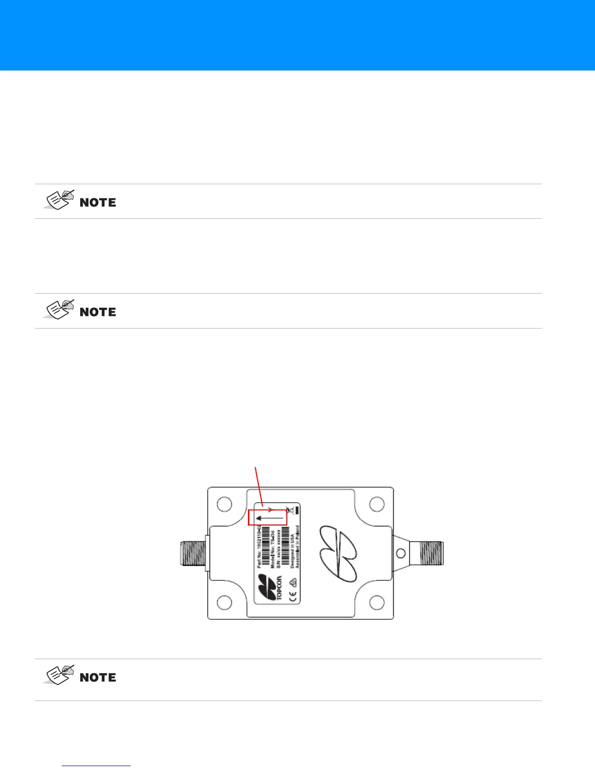
When installing the sensors, ensure that they are mounted parallel to the axis being measured (See
Figure 2-1 below). Locate surfaces that protect the sensor from physical damage and are convenient
for cable routing. When the position of the implement is at zero degrees (horizontal), make a note of
the direction of the arrow marker on the serial label (located on the top of the sensor). This direction
is needed during calibration. The calibration process uses 3D-MC to enter direction, orientation, and
other sensor variables.
TS-i3 Sensor Orientation
Figure 2-1: TS-i3 Sensor Orientation
When mounting the tilt sensors, begin with the Attachment/Bucket sensor to help
simplify cable routing.
The Dual Axis TS-i3 sensor is labeled TS-i3d.
Mount each tilt sensor within +/- 20° of the pivot centerline. Although this does not
ensure system performance, squaring the sensors to each part of the machine
makes for a cleaner looking installation.