System Components—Hardware and Software
1-3
P/N: 7010-1006
Introduction
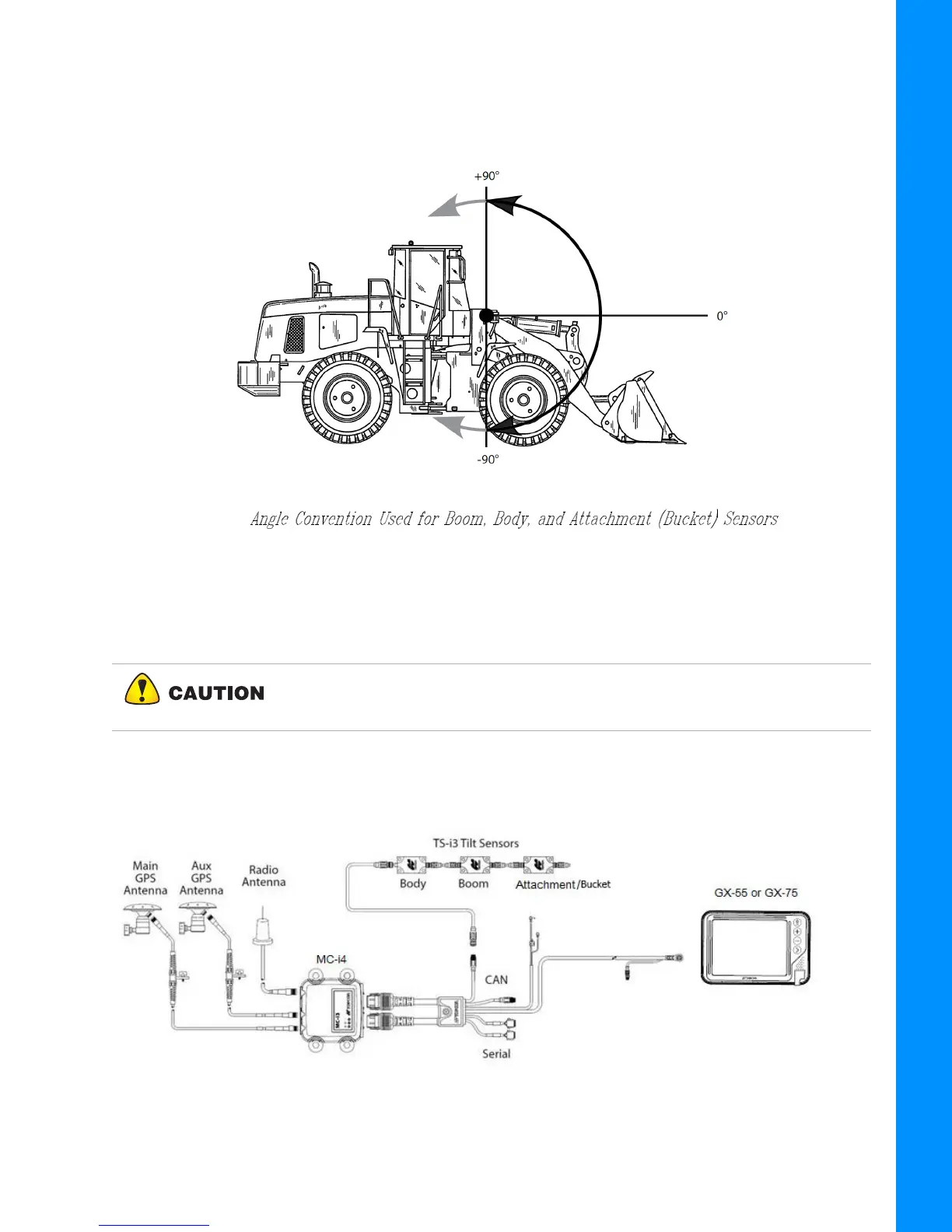
Sensor Angles
Sitting in the Cab facing forward, the Sensor Angles are 0° (straight ahead—horizontal),
+90° (straight up—vertical), and -90° straight down, see Figure 1-2.
Figure 1-2:
Basic Cable Connections
Figure 1-3 shows the basic cabling connections for the Wheel Loader system. When installing
hardware components, use the Topcon supplied fuse or fused power from the Wheel Loader.
Figure 1-3: Basic Cable Connections for the Wheel Loader System
Connect the System ground to the frame side of the Ground Disconnect
Switch, do not connect the ground directly to the Wheel Loader’s Battery
Terminal.