Sensor Filtering
4-6
P/N: 7010-1006
Calibration
5. Tap Next.
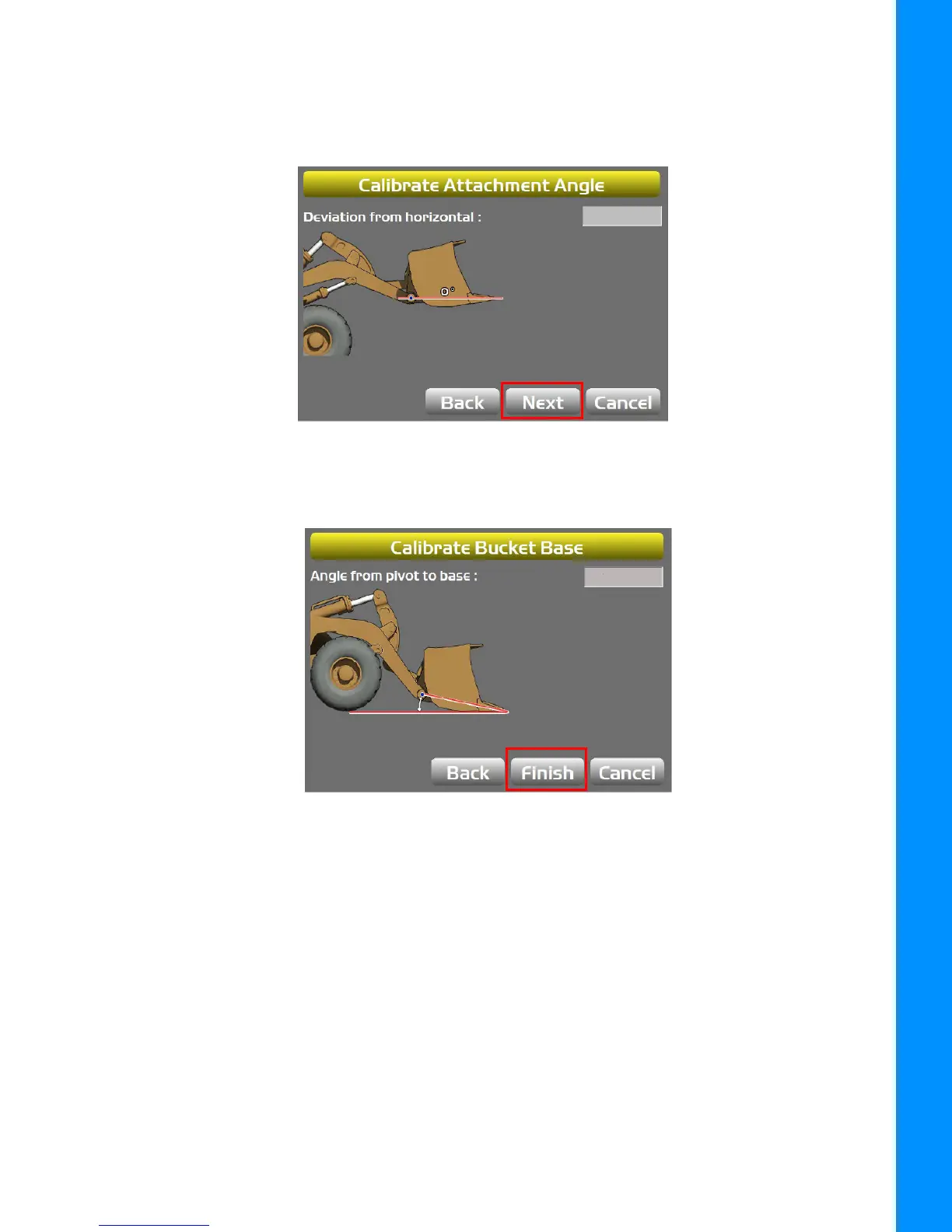
6. With the Bucket Pivot Point and the Bucket Teeth aligned at zero (0.0) degrees, tap Next
(Figure 4-7).
Figure 4-7: Calibrate Attachment Angle
7. Set the bottom of the Bucket flat on the ground and press Finish (Figure 4-8).
Figure 4-8: Calibrate Bucket Base
Sensor Filtering
The filter level for each sensor can be changed depending on the application and the operator’s
choice. A value of 4 (heavy filtering) will dampen sensor reaction, while a value of 1 (light filtering)
will cause faster sensor reaction.
1. Using the 3D-MC Software Interface, tap Topcon Menu Button > Control > Machine
>Setup. Select the applicable machine file and tap Edit.
2. Tap Next to navigate to the Loader Frame/Sensors screen (Figure 4-9).
3. Tap the Wrench Icon next to the Sensor ID that you will be adjusting.