− 10 −
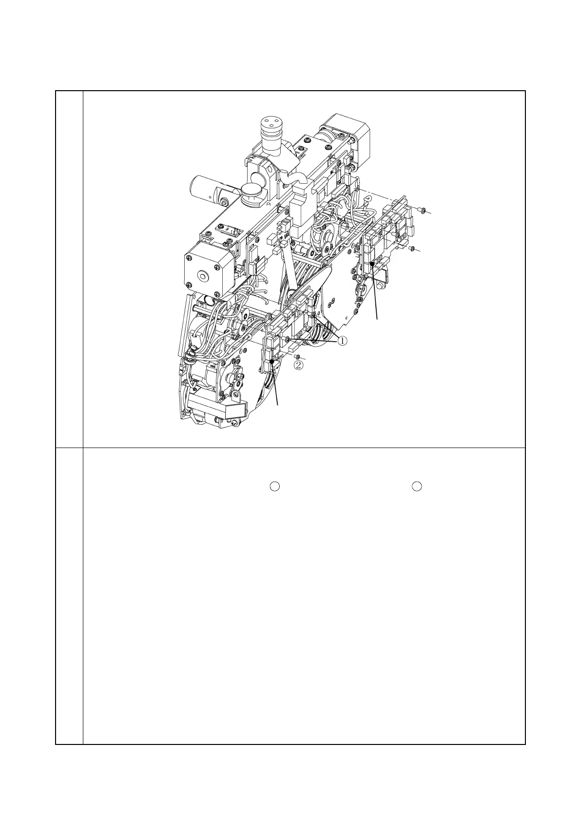
3-1-3 Removal of lens PCB
Illustration
Procedure
1. Remove the tape wires and all the connectors from the L PCB.
2. Remove the two screws CR3 × 4Ni
and one screw CR2.5 × 4Ni
. Then, remove the
L PCB.
3. Remove the R PCB in the same way as the L PCB.
Note: When installing, attach the insulation sheet.