17
5. SYSTEM CONFIGURATION
●
Range Pole Type
● Height to center of prism
The height to the center of the prism differs as shown below depending on the selection of prism/pole
combination. Read the following in conjunction with the above diagrams.
Pin Pole Type
h1: Height from the tip of the prism foot to the center of prism is 10 cm when mounting the 360°
Prism ATP1 on the adapter SB184 and stainless steel prism foot AP66.
h2: Height from the tip of the prism foot to the center of prism is 10 cm when mounting the 360°
Sliding Prism ATP1SII on the pin pole for ATP1SII PP2 and the prism is at the lowest position
on the pole. Graduations on the pin pole for ATP1SII PP2 are at 5cm intervals. Aligning the
top of the sliding prism with one of the graduations then sliding up or down to the next
graduation will result in a vertical movement of 5 cm. Maximum range of the sliding pole is 40
cm.
•Do not subject the prism to strong shock when set at the highest position on the pin
pole. Otherwise, the prism may slip downwards.
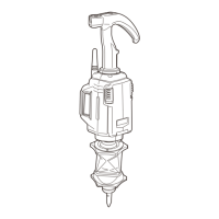
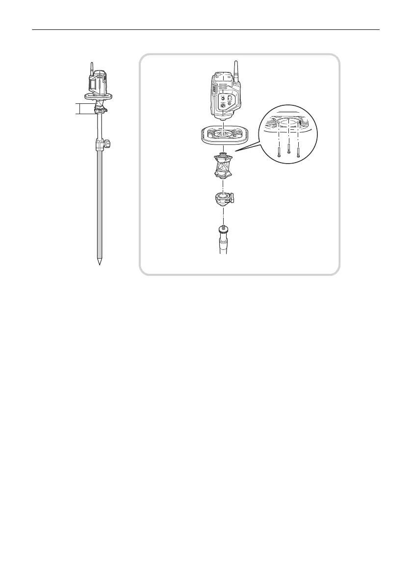
Range Pole Type
h3: Height from the base of the one-touch attachment to the center of prism is as follows when
mounting the 360° Prism ATP1 on the Range Pole.
5/8 inch Setting screw pole with SB179B: 74 mm
Protector
360° Prism
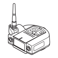
Remote
attachment
One-touch
SB179B
5/8 inch
Setting screw
(W5/8-11) pole
h3
Range pole
example
RC-5A
RP3
ATP1
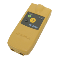
Controller