13
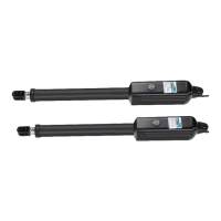
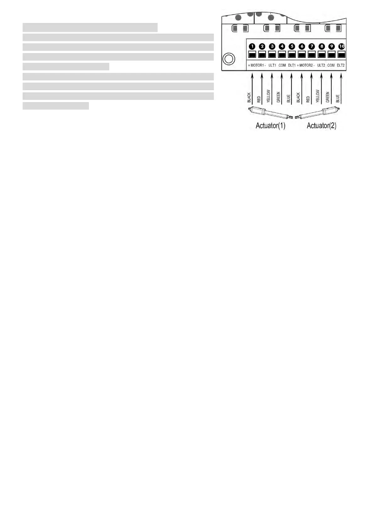
Motor connection for PUSH-TO-OPEN
The motors’ power wires and limit wires connection by “Push to
Open” is different from the connection by “Pull to Open”. So
motor 1 and motor 2 wires should be connected to the control box
as the instruction on the right.
Black wire should be inserted into the Motor+ terminal. Red wire
should be inserted into the Motor- terminal, the Yellow wire into
ULT1 terminal and the Blue wire into DLT1 terminal. Green wire is
still into COM terminal.
Warning Light (Included in some models, refers to the actual package)
The red wire of the warning light should be inserted into either +LAMP (#11) terminal, the white wire into the
LAMP- (#12) terminal.
Back-up Battery & Solar Panel & Solar Controller (optional)
If there is no solar panel to be used for charging the battery, then the “24V+” of the battery should be wired to
the BAT+ (#19) terminal. “24V-” should be wired to “BAT-” (#18) terminal.
The battery could also be charged by the solar panel & solar controller. Please refer to the manual instruction of
solar panel and controller separated for wire connection.
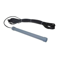
Photocell Beam System (PBS) (Included in some models, refers to the actual package)
Use a 2-core cable to connect the “- ~” terminal of the photocell’s emitter to the “14” terminal, the “+ ~” terminal
to the “13” terminal. Also the “- ~” and “+ ~” terminals of the photocell’s receiver should be connected to the
“14” and “13” terminals in parallel.
Use another 2-core cable to connect the “COM” terminal of the receiver to the “15” terminal, the “NC” terminal
to the “16” terminal.
Push Button (optional)
The push button should be wired to the GND (#16) and O/S/C (#17) terminals. The gate operator works
alternately by pushing the button (open-stop-close-stop-open).
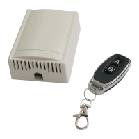
External Receiver (optional)
The BROWN wire of the external receiver should be connected into the “17” terminal.
The BLACK wire of the external receiver should be connected into the “16” terminal.
The RED wire of the external receiver should be connected into the “13” terminal.
Wired Keypad (24VDC) (optional)
The RED wire of the wired keypad should be connected into the “13” terminal.
The BLACK wire of the wired keypad should be connected into the “14” terminal.
The PURPLE wire of the wired keypad should be connected into the “16” terminal.
The BLUE wire of the wired keypad should be connected into the “17” terminal.
How to Program or Erase the Remote
The remote MUST be programed to the opener BEFORE OPERATING. Please follow the steps to
program the remote.
Activate the opener only when gate is in full view, free of obstruction and properly adjusted. No one
should enter or leave gate area while gate is in motion. DO NOT ALLOW CHILDREN to operate push
button or remote. DO NOT ALLOW CHILDREN TO PLAY NEAR THE GATE.
If you purchase additional remote controls, the gate opener must be programmed to accept the new
remote code.
If you lose one of any remote control, please erase and reprogram all other remote controls to have a
new code for safety.