7. After the piping is connected, the alignment at the coupling should be checked once again. It should be possible to rotate the
rotating assembly easily by hand on the coupling, if the stuffing boxes are not packed (see section 3.2.1).
8. Dowel the driver (see section 2.1.6.).
9. Before the pump is started up for the first time, it is essential to check the direction of rotation of the driver, with the pump
uncoupled. Remember that even a short run in reverse rotation or a short period of dry running can result in serious
damage to the pump.
The correct direction of rotation of the pump is indicated by an arrow on the drive end bearing housing.
Turbine driven pumps should have their turbine over speed trip tested with the pump uncoupled.
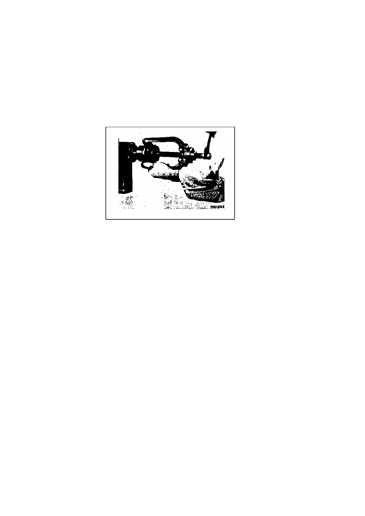
Fig.9 Coupling Extractor
3.2. Fitting and dismantling the coupling
Flexible couplings should either be heated to 180 °C ( 350 °F ) approx, before fitting or removing, or this work should be
done with the aid of a suitable coupling extractor ( see fig. 9 ). Never drive the coupling onto the shaft with a hammer.
3.2.1. Aligning the coupling
Faulty alignment will result in damage to the flexible components of the coupling, and will also damage the pump and motor
bearings.
In order to align the shafts, the pump and driver are set on the grouted-in bed plate as shown on the General Arrangement
Drawing, and pushed towards one another until the pre-scribed gap between the two coupling halves has been attained. Then
the coupling can be aligned by means of a straight edge and gauge block (fig. 10a) ; the coupling is correctly aligned ifa=a] and
b = bj; furthermore the axial gap between the faces of the coupling halves should remain the same right around the periphery of
the coupling.
We can supply a special alignment jig on request (see fig. 10b) which greatly facilitates coupling alignment. When this jig is
used, the coupling can be considered correctly aligned if the tolerance, both in the axial and radial planes measured at the tips
at four points around the periphery, at 90° intervals, does not exceed 0.05 mm in any case. This control should be repeated
after connection of the pipelines.
-
-