An isolating valve should only be incorporated in a suction lift line, if more than one pump is connected too common suction
line. In such cases, the valve should be installed with its stem horizontal, or pointing vertically downwards, to prevent the
formation of air pockets.
If this proves inconvenient, and the valve has to be installed with its stem vertically upwards, it should be provided with a
sealing water connection, or a so called water cup, to prevent the ingress of air through the gland on the valve stem.
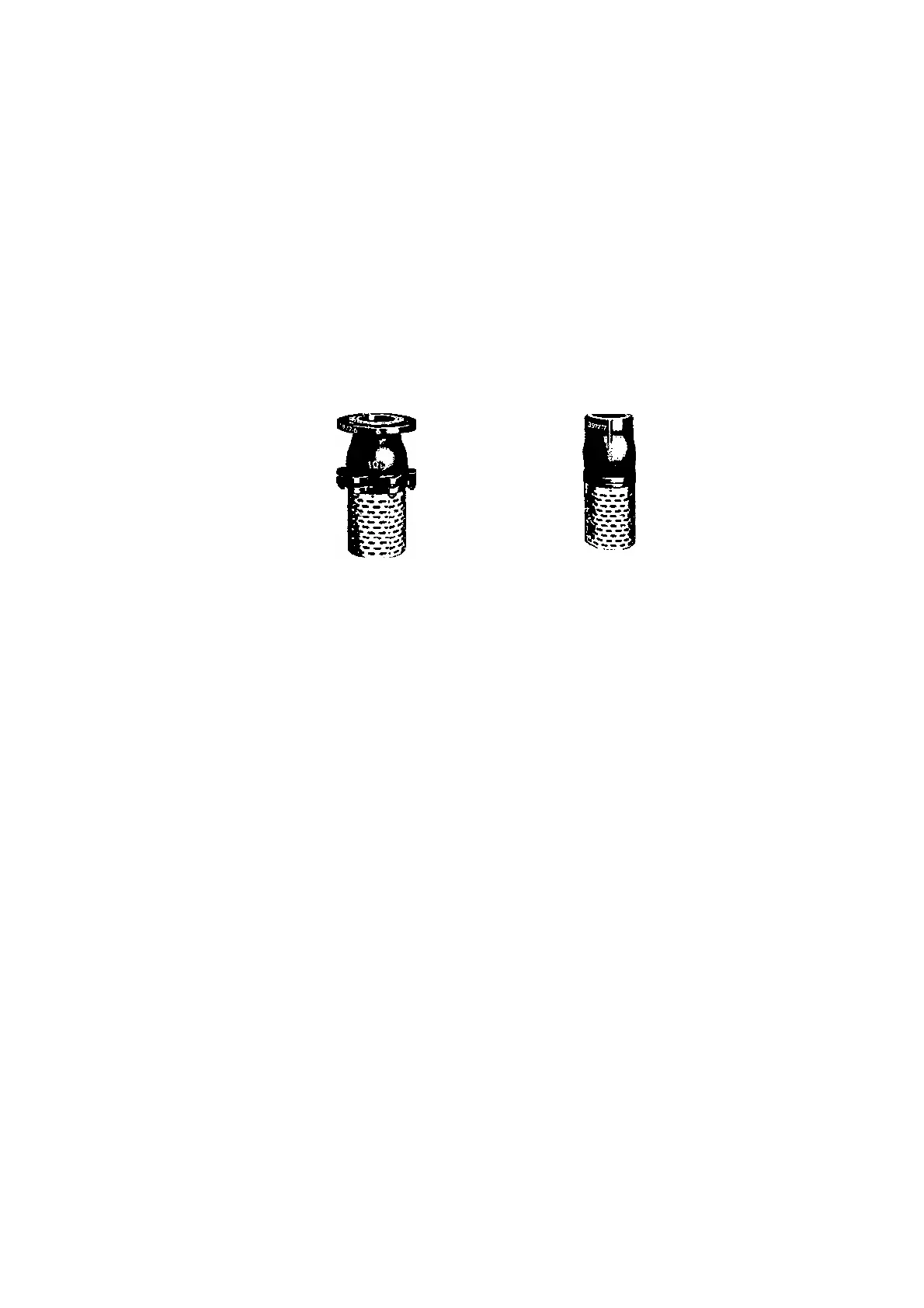
Pumps lifting from a suction tank or suction pit should have a strainer basket fitted to the mouth of the suction line, in order
to keep coarse impurities away from the pump.
The strainer basket is usually combined with a foot valve, which enables the suction lift line to be primed with fluid before
starting the pump (see fig. 13). The strainer basket should be installed at least 0.5 meters (18 ins.) below the minimum water
level in the pit, and at least 0.5 meters (18 ins.) above the pit floor, to prevent either air or sand or sludge being entrained into
the pump (see fig. 11 a) .
Fig. 13 Suction strainer basket with foot valve
Positive suction head lines should preferably be provided with an isolating valve, so that the pump can be isolated from its
supply source required.
3. 5. 2. Valves and fittings in discharge line
Each pump should be provided with an isolating valve in the discharge line, situated as close to the pump as possible. A
part from isolating the discharge line from the pump, this valve can be used to throttle the discharge flow in order to achieve the
desired operating duty or to avoid over loading the driver.
We also recommend the installation of a non-return valve between the pump discharge nozzle and the isolating valve in the
discharge line. This can be either a check valve, a non-return valve, or by-pass non-return valve (automatic leak-off valve) - see
section 3.5.3., according to requirements.
The object of the non-return valve is to prevent a reverse flow of fluid from the discharge line into the pump, when the latter
is suddenly shut down, and to protect it from possible damage arising from water hammer, i.e. violent pressure pulsations.
A sticking or leaky non-return valve or check valve will cause reverse rotation of the pump and may result in damage if the
shaft nut becomes slack. This may arise if the pressure in the discharge line is higher than that in the positive suction line when
the pump is stopped, causing reverse flow of the fluid.
Please note that these reverse rotation speeds can attain very high values, especially when the pump is pumping against
an air or gas cushion. In this event, gas will penetrate inside the pump and expand there.
It is recommended to provide two non - return valves in series in such cases.
3.5.3. By-pass non-return valve
The by-pass non-return valve, or automatic leak-off valve is a safety device, the purpose of which has already been
described in section 2.3. It is fitted in close proximity to the pump, always between the pump and the isolating valve in the dis-
charge line (never down-stream of the isolating valve).
- 11 -