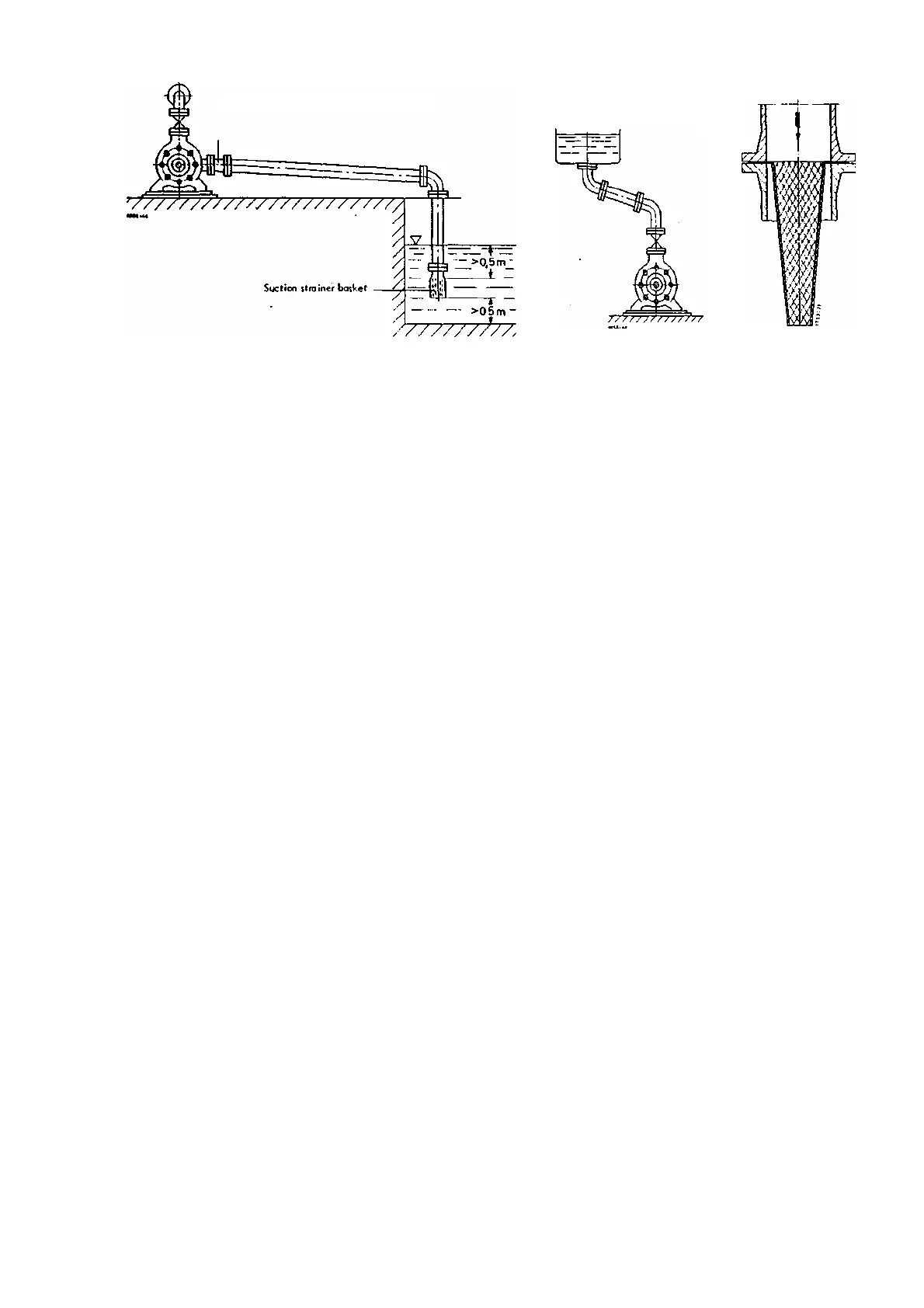
Eccentric reducer (fitted belly down)
Fig. 12
Fi
g
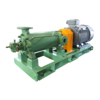
.11a Suction lift line
Fig. 11b
For positive suction head lines, (see fig. 11b), the same considerations apply as for suction lift lines, as regards features
and laying of the line. The horizontal sections of the line should however be laid with a gently rising incline towards the suction
vessel. If it is impossible to avoid apexes in the suction line, each apex should be provided with a vent cock.
Before the pumping set is commissioned, the suction lines and vessels must be thoroughly cleaned and flushed.
Unfortunately, foreign matter, including welding beads, pipe scale etc. tends to become detached from the piping only after a
considerable period of service, particularly when a hot fluid is pumped. In order to prevent these foreign bodies from penetrating
inside the pump, it is necessary to incorporate a strainer in positive suction head lines.
This strainer should have a total area of holes equal to three to four times the pipe cross-section, in order to avoid too great
a pressure drop when it becomes choked with foreign bodies.
Conical strainers of the type illustrated in Fig. 12 have proved very satisfactory for this purpose, and are recommended;
they should be made of corrosion-resistant materiaI.
The pressure at the pump suction nozzle should be checked at regular intervals. If it drops, this indicates that the suction
strainer should be removed and cleaned. After severer weeks of operation, when no more foreign bodies are anticipated, the
strainer can be permanently removed.
3. 4. 2. Discharge Piping
The hydrostatic test pressure prescribed in DIN 2401 specification only applies to individual lengths of pipe and not to the
complete, finally assembled discharge line.
The latter is usually tested at a pressure equal to the maximum operating pressure anticipated.
Discharge lines are usually sized for flow velocities of 3 m/sec. (10 ft/sec).
3. 5. Valves and fittings
Only those valves and fittings (i.e. isolating or control valves, non - return valves and check valves) are described here
after, which are incorporated in the suction line, or close to the pump itself in the discharge line.
3.5.1. Valves and fitting in suction line (suction lift line or positive suction head line).
Isolating valves in the suction lift line or the positive suction head line are solely intended to isolated the line. They
must always be kept fully open while the pump is running.
- 10 -